Lock and release mechanism of child resistant unit dose package

a technology of locking mechanism and child-resistant unit, which is applied in the direction of transportation and packaging, packaging type, drawer-and-shell containers, etc., can solve the problems of karow package being susceptible to unintentional or accidental release, packaging being difficult to open for the elderly, and being vulnerable to children's efforts to gain access to the contents of the packag

Inactive Publication Date: 2005-04-05
HOWELL PACKAGING DIV OF FM HOWELL
View PDF25 Cites 86 Cited by
  • Summary
  • Abstract
  • Description
  • Claims
  • Application Information

AI Technical Summary

Benefits of technology

It is also an object of the invention to provide a child resistant unit dose package having a unique lock and release mechanism that prev...

Problems solved by technology

Seeley discloses a tamperproof package that requires a substantial amount of dexterity on the part of the user, which may render the package difficult to open for the elderly.
In particular, Karow states the locking means disclosed by Johnstone et al. is susceptible to unintentional or accidental rel...

Method used


Image

  • Lock and release mechanism of child resistant unit dose package
  • Lock and release mechanism of child resistant unit dose package
  • Lock and release mechanism of child resistant unit dose package

Examples


first embodiment

the invention will now be explained.

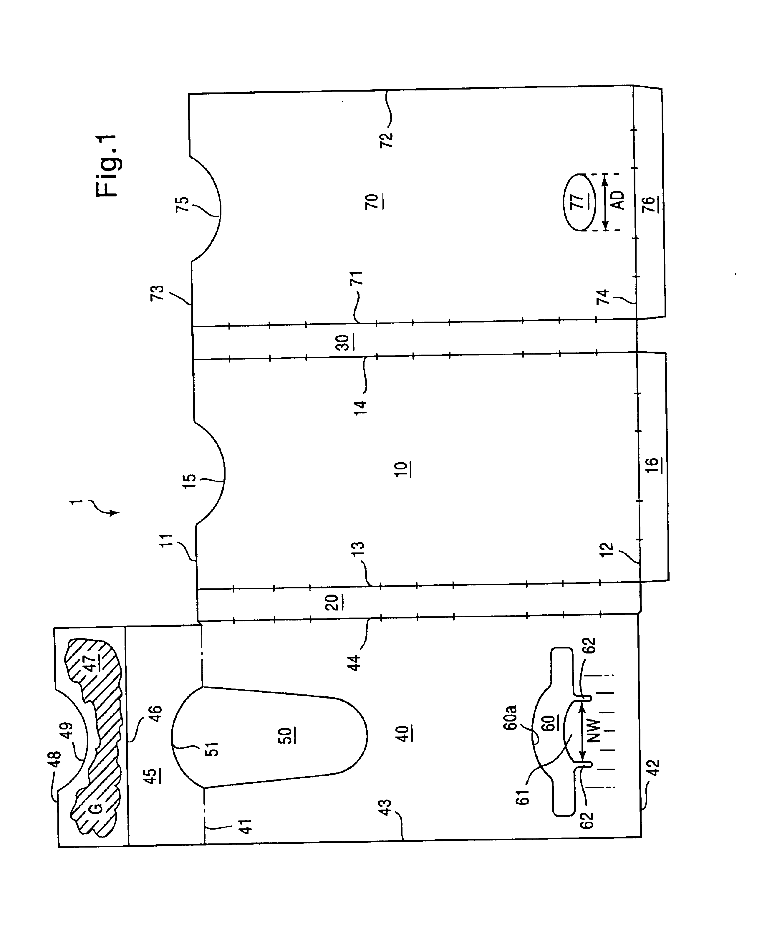
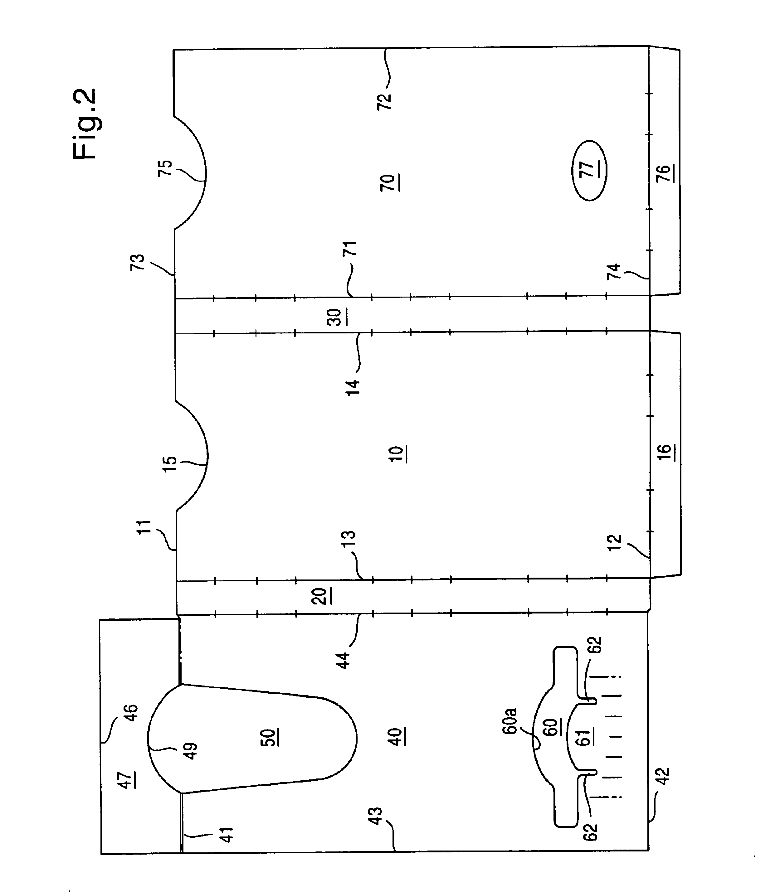
Referring to FIG. 1, the outer sleeve 1 of the package is formed from a flat, substantially rectangular shaped single blank, ideally made from paperboard. However, it is within the scope of this invention to use any suitable material well known or later developed in the art, such as, for example, paper, plastic, metal, natural or man made, and the like. Furthermore, although not illustrated but well understood in the art, it is within the scope of this invention to use any suitable geometric shape, such as, for example, square, trapezoidal, circular, oval, and the like to form the outer sleeve 1.

The outer sleeve 1 includes a first panel 10 separated from a second panel 40 by a first side panel 20. The first panel 10 and first side panel 20 are separated by score line 13 while the first side panel 20 is separated from the second panel 40 by score line 44. The first panel 10 is also separated from a third panel 70 by a second side panel 30. The firs...

second embodiment

the invention will now be explained.

Referring to FIGS. 10-14, the outer sleeve 1a of the package is similar to the sleeve 1 described above with regards to the first embodiment. However, the node 61 and legs 62a, 62a of the second panel 40a are modified and the aperture 77 of the third panel 70 is replaced with a pair of release buttons 78, 78. Otherwise, similar features are identified with like reference numerals and the description of such similar features is omitted to avoid redundancy.

As shown in FIGS. 10-13, the outer sleeve 1a for the package of the second embodiment also includes a second cut away 60 formed in a region near the bottom edge 42 of the second panel 40a. However, the pair of legs 62a, 62a which define the node 61 and prevent the entire length of the node 61 from deflecting are formed by elongations that are oblique relative to the bottom edge 42. Furthermore, the node 61 of the second embodiment is bifurcated by a cut line 63 into first and second node portions ...


PUM

PropertyMeasurementUnit
Diameteraaaaaaaaaa
Electrical resistanceaaaaaaaaaa
Widthaaaaaaaaaa

Abstract

A lock and release mechanism of a unit dose package has a cut away formed in the second panel of an outer sleeve of the package, the cut away having a pair of legs extending therefrom and defining a node therebetween. A cut line and a throat region are formed in an end flap of first and second side panels, respectively, of a slide card to bifurcate each end flap into first and second engaging segments. The first and second engaging segments engage an engaging surface of a cut away formed in a second panel of the outer sleeve to prevent the slide card from unintentionally sliding within the outer sleeve. A release feature is formed in the third panel of the outer sleeve. The first and second engaging segments are disengaged from the engaging surface of the cut away by depressing the node via the release feature.

Description

BACKGROUND OF THE INVENTION1. Field of the InventionThis invention relates to a unit dose package having a unique lock and release mechanism that prevents a sliding card from being unintentionally disengaged from an outer sleeve, wherein the unit dose package provides a user with access to the solid articles or products contained in the sliding card.2. Description of the Related ArtIt is common practice to use blister packages to package small solid articles or products which may be dispensed from the package by applying pressure to the blister to force the article or product from an individual blister or capsule through a rupturable membrane. Since this type of packaging is typically used for marketing medicines, the invention will be referred to herein with respect to a package particularly suitable for such use, but it should be understood that the package may be used for other products as well. Recently, a substantial effort has been directed toward providing packaging that cont...

Claims


Application Information

Patent Timeline
IPC IPC(8): B65D5/44B65D5/00B65D5/38B65D75/28B65D75/34B65D75/32
CPCB65D75/327B65D83/0463B65D2215/04
Inventor PALIOTTA, MICHAELHOWELL, GEORGE
Owner HOWELL PACKAGING DIV OF FM HOWELL
Why Eureka
Try Eureka