Canted head-mounted light

a head-mounted light and canted technology, applied in the field of headlamps, can solve the problems of adsorption of the profile and weight of the lamp

Inactive Publication Date: 2005-04-12
ZEN DESIGN GROUP
View PDF15 Cites 108 Cited by
  • Summary
  • Abstract
  • Description
  • Claims
  • Application Information

AI Technical Summary

Problems solved by technology

This is especially true during prolonged activities that require unfettered use of the hands of a headlamp wearer.
Alternatively, a cumbersome support housing is built around the pivot to support and encompass the same thereby adding to the profile and weight of the lamp.

Method used


Image

  • Canted head-mounted light
  • Canted head-mounted light
  • Canted head-mounted light

Examples


Embodiment Construction

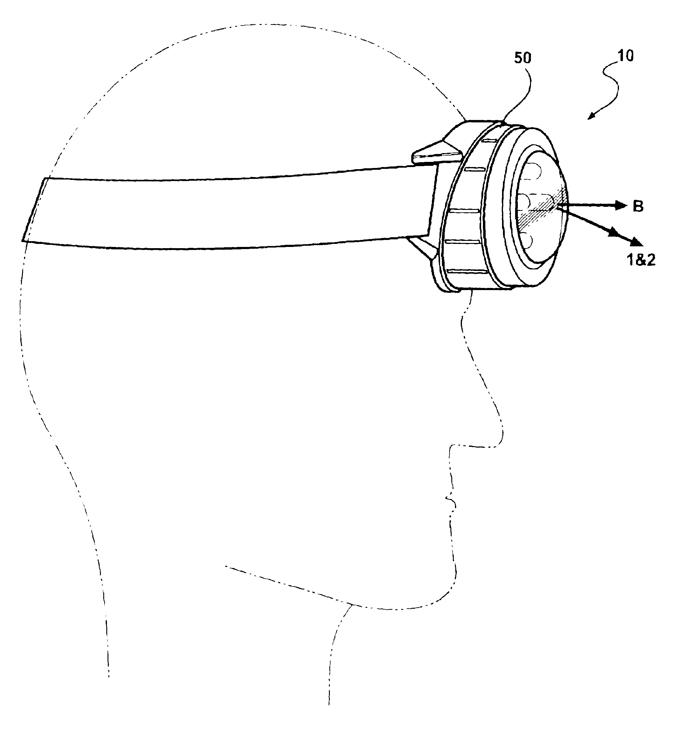
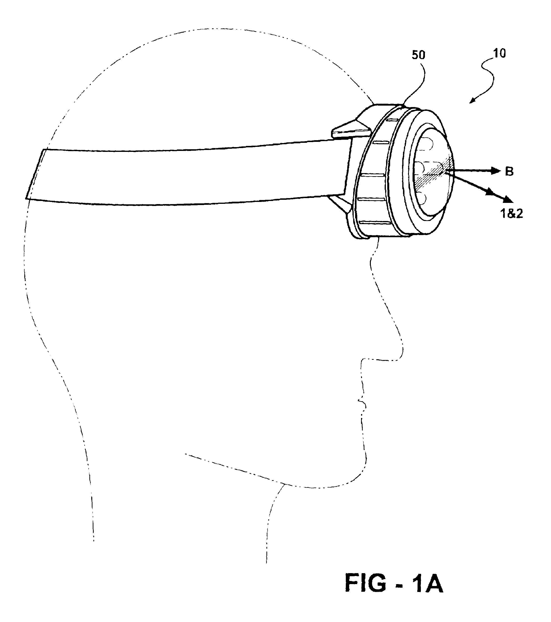
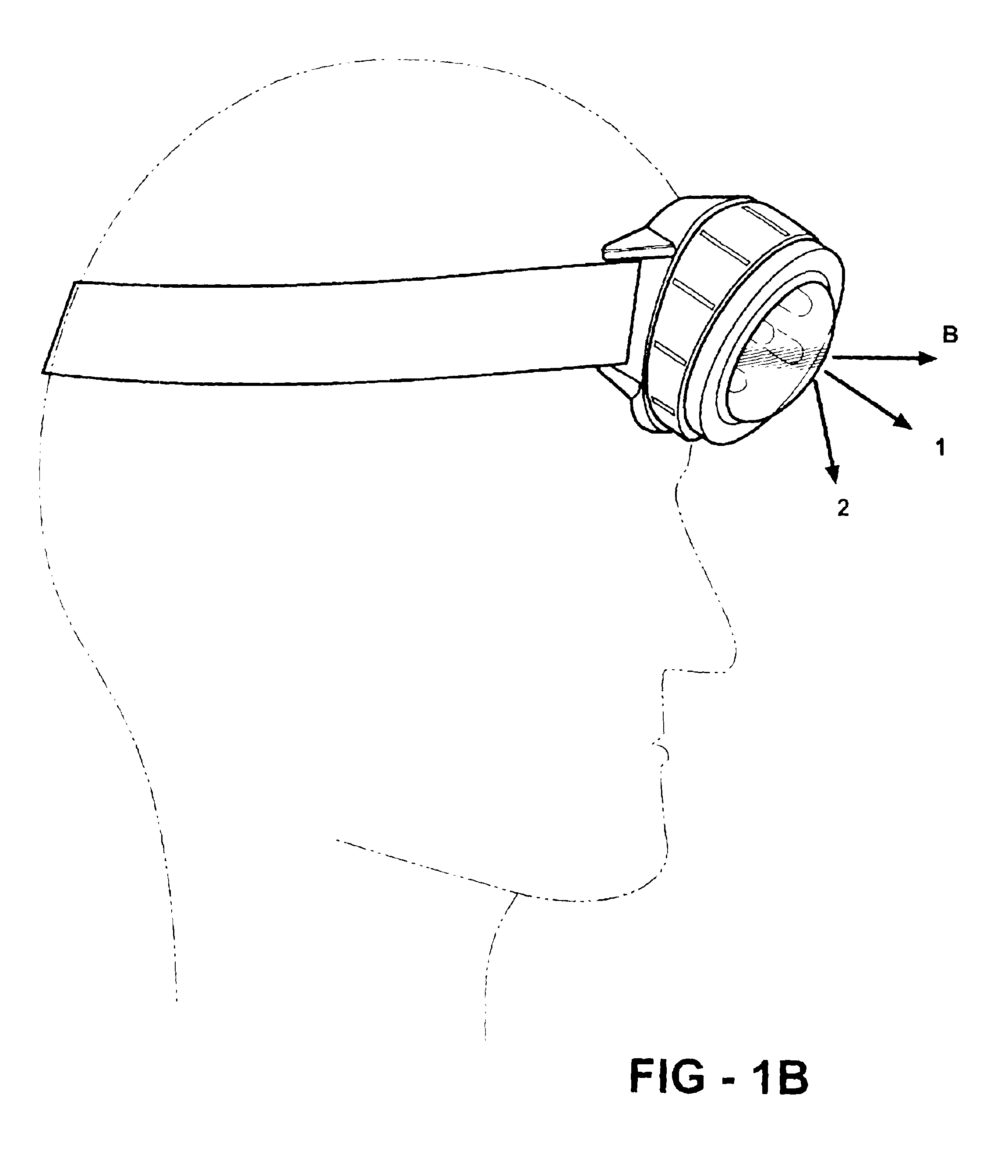
The present invention has utility as lamp mountable to the head of a wearer or incorporated into headgear. The present invention provides a rugged and compact headlamp where the lighting assembly cants relative to a static base. The front face of a headlamp base and the rear surface of a bezel incorporated into the light assembly are complementary bevel cut features such that rotation of the bevel cut rear surface of the bezel relative to the base changes the attitude of the light assembly. The present invention details a novel canted headlamp and process for canting a light assembly relative to a static base to adjust light projection attitude.

Referring now to FIGS. 1-3, an inventive headlamp is shown generally at 10. A base 12 is adapted to secure to the head of a wearer by way of a strap 14. The base having conventional strap engaging fixtures such as posts adapted to receive a spring-loaded hinge pin (not shown) affixed to the strap 14. In the preferred embodiment, the base 12 i...


PUM


Abstract

A headlamp includes a base having a front face defining a first imaginary plane along the front face and a first imaginary line orthogonal to the first plane. A light assembly is rotatably secured about the front face to the base. The light assembly includes a bezel having a rear surface defining a second imaginary plane along the rear surface and a second imaginary line orthogonal to the second plane so that the intersection of the first line and the second line defines a rotation angle that varies with the rotation of the light assembly relative to the base, thereby changing the attitude of the headlamp light assembly.

Description

FIELD OF THE INVENTIONThe present invention generally relates to headlamps and, more particularly, to headlamps having a movable mount for attitude adjustment of a light beam emanating therefrom.BACKGROUND OF THE INVENTIONHeadlamps, whether attached directly to the head of a user or integrated into protective headgear, are useful operating under low ambient light conditions. This is especially true during prolonged activities that require unfettered use of the hands of a headlamp wearer. Additionally, depending on the activities of a wearer, it is often advantageous to be able to adjust the attitude of the headlamp to selectively light an area about the wearer. A wearer might include a motorcyclist, a bicyclist, a firefighter, a miner, a construction worker, a hiker, a farm worker, a hunter or a naturalist.Prior art attempts to provide an adjustable attitude headlamp have resorted to a diametric pivot joint to adjust the angle of the light source relative to the headgear and / or the ...

Claims


Application Information

Patent Timeline
Patent Type & Authority Patents(United States)
IPC IPC(8): A42B3/04F21L4/00F21V14/02F21V14/00F21V23/04F21V21/08F21V21/084F21L4/04
CPCA42B3/044F21L4/04F21V14/025F21V21/145F21Y2101/02F21V23/0414F21V21/084F21Y2115/10
Inventor YU, SUNTIEFEL, ANDREWPERRIN, DAVID
Owner ZEN DESIGN GROUP
Why Eureka
Try Eureka