Filter element having sealing members and methods

a filter element and sealing member technology, applied in the direction of filtration separation, combustion-air/fuel-air treatment, separation process, etc., can solve problems such as damage to whatever system

Inactive Publication Date: 2005-04-12
DONALDSON CO INC
View PDF48 Cites 112 Cited by
  • Summary
  • Abstract
  • Description
  • Claims
  • Application Information

AI Technical Summary

Problems solved by technology

If it is difficult or inconvenient to service the filter element, the user may delay the proper servicing, which can cause damage to whatever system is being filtered.

Method used


Image

  • Filter element having sealing members and methods
  • Filter element having sealing members and methods
  • Filter element having sealing members and methods

Examples


Embodiment Construction

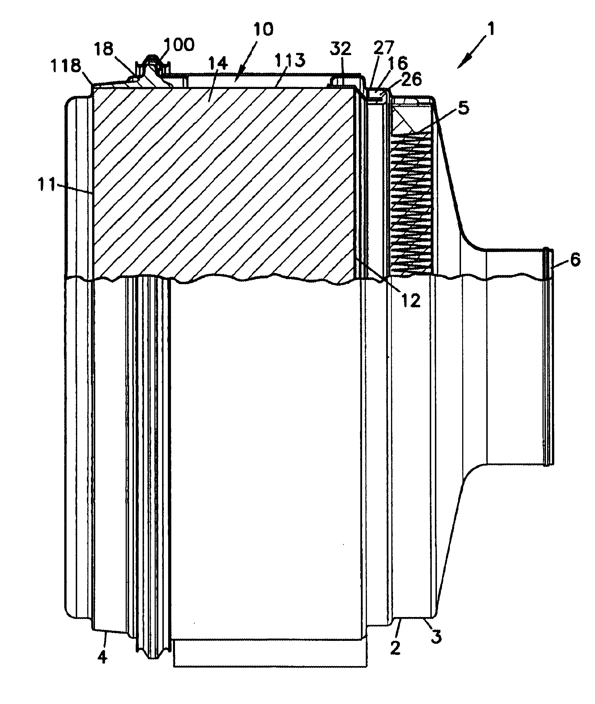
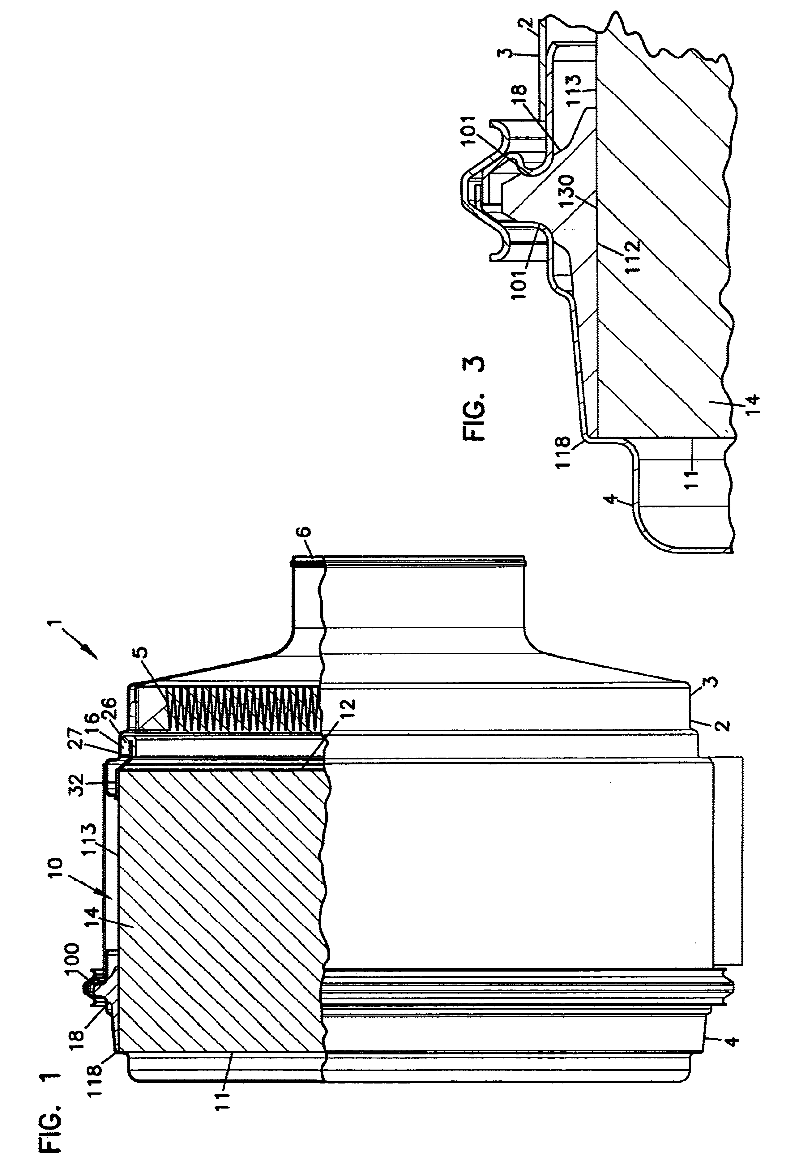
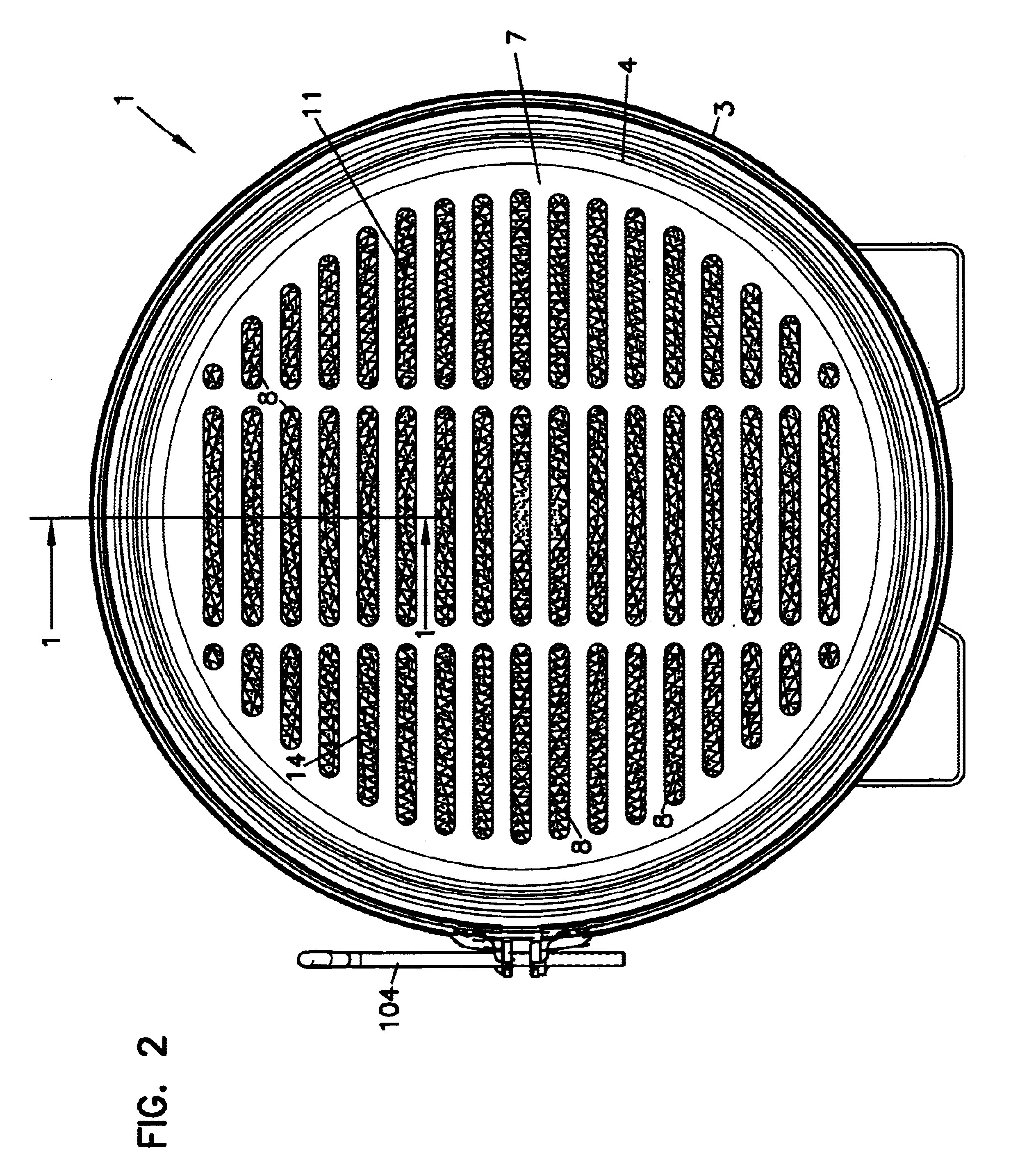
FIG. 1 depicts an air cleaner 1, including a housing 2 with a filter element 10 operably mounted therein. The housing 2 preferably includes a body member 3 and a removable cover 4. The filter element 10 is selectively removable and replaceable from the housing 2 by removing the cover 4 from the body member 3, providing access to the element 10.

The air cleaner 1 is usable for cleaning fluid, such as gas, in particular air. The filter element 10 is configured to permit straight through flow. By the term “straight through flow,” it is meant that the fluid flows directly through the filter element 10, entering at an inlet face 11 and exiting in a same direction at an opposite, outlet face 12 without turning a corner. The filter element 10 includes filter media 14 that is configured to filter particulates from the gas stream entering at the inlet face 11, such that the gas stream exiting the outlet face 12 is at least partially clean (i.e., free of particulates). As can also be seen in F...


PUM

PropertyMeasurementUnit
densityaaaaaaaaaa
lengthaaaaaaaaaa
heightaaaaaaaaaa

Abstract

A filter arrangement includes a media construction comprising a corrugated sheet secured to a flat sheet rolled into a coiled construction. A frame and a first seal member are provided. The frame secures the first seal member to the coiled construction. The first seal member is preferably oriented to form a radial seal with a housing. A second seal member is secured to the outer annular surface of the coiled construction. The second seal member includes a gasket extension having first and second opposite ends; an attachment portion; and a protrusion extending from the attachment portion. The second seal member is preferably oriented to form an axial seal with a housing. Air cleaners preferably utilizing filter arrangements as described herein operably installed within housings. Methods of installing, filtering, assembling, and servicing preferably include arrangements as described herein.

Description

TECHNICAL FIELDThis disclosure describes filter constructions for filtering fluids, such as gas or liquid. In particular, this disclosure describes a straight-through flow filter element with sealing members, and methods for using and assembling such a filter element.BACKGROUND OF THE INVENTIONStraight through flow filter elements have been used in systems for cleaning fluid passing therethrough. Straight through flow filter elements typically have an inlet face and an oppositely disposed outlet face. In this manner, fluid flows in one direction upon entering the filter element at the inlet face and will have the same direction of flow as it exits the outlet face. Typically, straight through flow filter elements will be installed in a duct or housing of some type. After a period of use, the filter element will require servicing, either cleaning or a complete replacement of the filter element. If it is difficult or inconvenient to service the filter element, the user may delay the pr...

Claims


Application Information

Patent Timeline
Patent Type & Authority Patents(United States)
IPC IPC(8): B01D46/52B01D29/07B01D46/00F02M35/024B01D46/10
CPCB01D46/0004B01D46/0005B01D46/0095B01D46/10B01D46/527B01D46/4227B01D2271/027B01D2267/40B01D2271/02B01D46/00
Inventor XU, JIANKUHN, JOHN DAVIDKREITINGER, EDWARD J.BISHOP, WAYNE R. W.GIESEKE, STEVEN SCOTT
Owner DONALDSON CO INC
Why Eureka
Try Eureka