Supercharge Your Innovation With Domain-Expert AI Agents!

Combination ratchet/breaker bar wrench

a ratchet and breaker bar technology, applied in the field of hand tools, can solve the problems of parts quickly wearout and the ratchet is not a strong tool

Inactive Publication Date: 2005-05-03
TREMBLAY THEODORE C +1
View PDF7 Cites 12 Cited by
  • Summary
  • Abstract
  • Description
  • Claims
  • Application Information

AI Technical Summary

Benefits of technology

"The invention is a combination wrench that can be used as a ratchet wrench and a breaker bar. The wrench has a handle with a ratchet wrench spline and a breaker bar spline at one end, allowing for easy storage when not in use. The wrench also has a ratchet mechanism with two drive splines that can apply different amounts of torque to a socket wrench. The method involves attaching the wrench to the first drive spline, applying torque, and then attaching it to the second drive spline for another amount of torque. The combination wrench provides flexibility and efficiency in applying torque to different situations."

Problems solved by technology

However, ratchets are not a strong tool.
These parts will wear out quickly if forces of over-rated stress are applied to the ratchet wrench.

Method used


Image

  • Combination ratchet/breaker bar wrench
  • Combination ratchet/breaker bar wrench
  • Combination ratchet/breaker bar wrench

Examples


Embodiment Construction

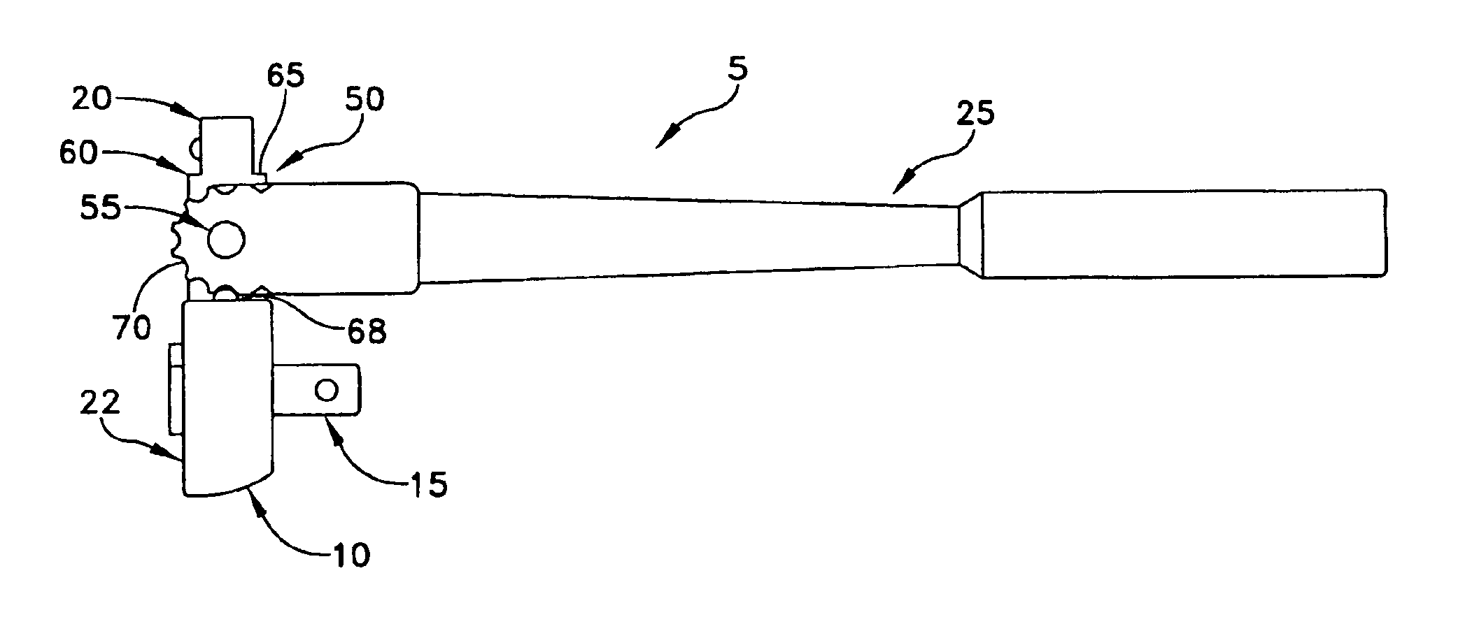
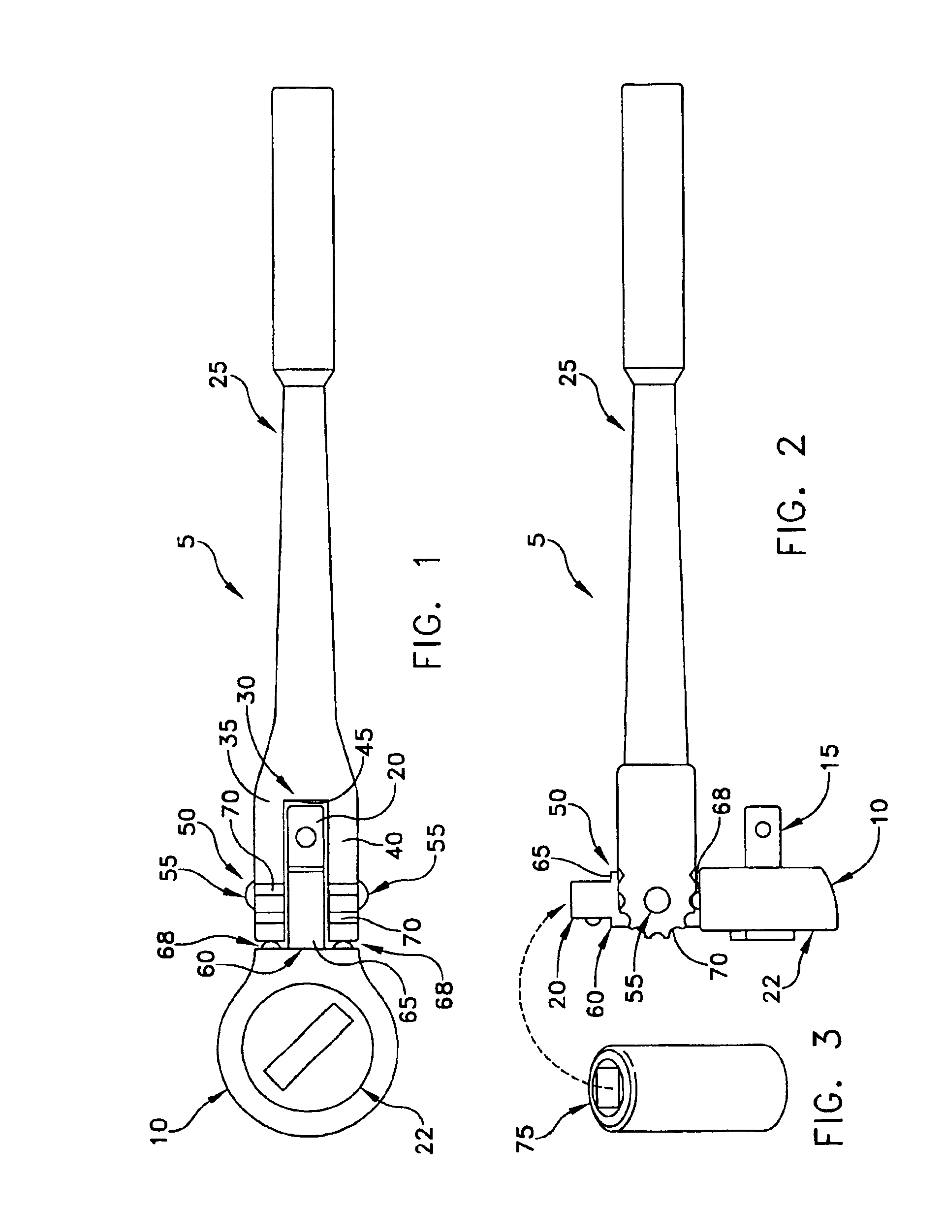
[0033]Referring to FIGS. 1 and 2, and in a preferred embodiment of the present invention, there is shown a combination wrench 5 having a ratchet head 10 with a ratchet drive spline 15 (FIG. 2) and a breaker bar drive spline 20. A ratchet mechanism 22 is disposed in ratchet head 10 to selectively actuate ratchet drive spline 15. A handle 25 is in pivotal attachment with socket head 10.

[0034]Handle 25 forms a fork portion 30 having a first arm 35 and a second arm 40 with an opening 45 formed therebetween. A connector portion 50 includes a passageway formed through first arm 35 and second arm 40, respectively. A pivot pin 55 is disposed through the passageway in the first arm 35 and the second arm 40.

[0035]A connection portion 60 of socket head 10 comprises a narrow section 65 configured for disposition between arm 35 and arm 40 of fork portion 30. Narrow section 65 forms a passageway therethrough configured to receive pivot pin 55 therein.

[0036]Still referring to FIGS. 1 and 2, and in...


PUM


Abstract

Apparatus and methods for applying torque to a socket wrench are disclosed. The apparatus comprising a handle, a ratchet head, the handle and the ratchet head pivotally joined to one another, a ratchet mechanism having a first drive spline and a rotation control, the first drive spline extending substantially orthogonal to the longitudinal axis of the ratchet head, the first drive spline selectively rotatable with respect to the ratchet head, and the first drive spline configured to apply a first given torque to the socket wrench, and a second drive spline extending substantially parallel to the longitudinal axis of the ratchet head, the second drive spline fixedly secured to the ratchet head, and the second drive spline configured to apply a second given torque to the socket wrench.

Description

REFERENCE TO PENDING PRIOR PATENT APPLICATION[0001]This patent application claims benefit of (1) pending prior U.S. Provisional Patent Application Ser. No. 60 / 511,241, filed Oct. 14, 2003 by Theodore C. Tremblay et al. for COMBINATION RATCHET BREAKER BAR WRENCH, and (2) pending prior U.S. Provisional Patent Application Ser. No. 60 / 538,828, filed Jan. 23, 2004 by Theodore C. Tremblay et al. for RATCHET-BREAKER-BAR-WRENCH, which patent applications are hereby incorporated herein by reference.FIELD OF THE INVENTION[0002]This invention is related to hand tools in general, and more particularly to hand tools for applying torque using a socket wrench and a breaker bar.BACKGROUND OF THE INVENTION[0003]As it is well known, a ratchet wrench facilitates the removal of fasteners such as nuts and bolts. However, ratchets are not a strong tool. A ratchet wrench should not be used to remove a tight bolt, such as a head bolt on an engine, or corroded fasteners, etc.[0004]The ratchet mechanism is u...

Claims


Application Information

Patent Timeline
Patent Type & Authority Patents(United States)
IPC IPC(8): B25G1/00B25F1/00B25G1/06B25F1/04B25B13/46B25B23/00
CPCB25B13/461B25G1/063B25F1/04B25B23/0028
Inventor TREMBLAY, THEODORE C.TREMBLAY, GARY S.
Owner TREMBLAY THEODORE C
Features
  • R&D
  • Intellectual Property
  • Life Sciences
  • Materials
  • Tech Scout
  • Unparalleled Data Quality
  • Higher Quality Content
  • 60% Fewer Hallucinations
Learn More