Fuel injection device for an internal combustion engine

a fuel injection device and internal combustion engine technology, which is applied in the direction of fuel injecting pumps, liquid fuel feeders, machines/engines, etc., can solve the problems of reducing reducing the quantity of fuel available for injection, and reducing so as to increase the efficiency of the fuel injection apparatus, increase the pressure available for injection, and reduce the effect of pressure or pressure increase rapid

Inactive Publication Date: 2005-05-17
ROBERT BOSCH GMBH
View PDF2 Cites 18 Cited by
  • Summary
  • Abstract
  • Description
  • Claims
  • Application Information

AI Technical Summary

Problems solved by technology

When the second control valve is open, though, fuel flows out of the pump working chamber via the control pressure chamber, thus reducing the fuel quantity available for injection out of the fuel quantity supplied by the pump piston and also reducing the pressure available for the injection.
It follows from this that the efficiency of the fuel injection apparatus is not optimal.

Method used


Image

  • Fuel injection device for an internal combustion engine
  • Fuel injection device for an internal combustion engine
  • Fuel injection device for an internal combustion engine

Examples


Embodiment Construction

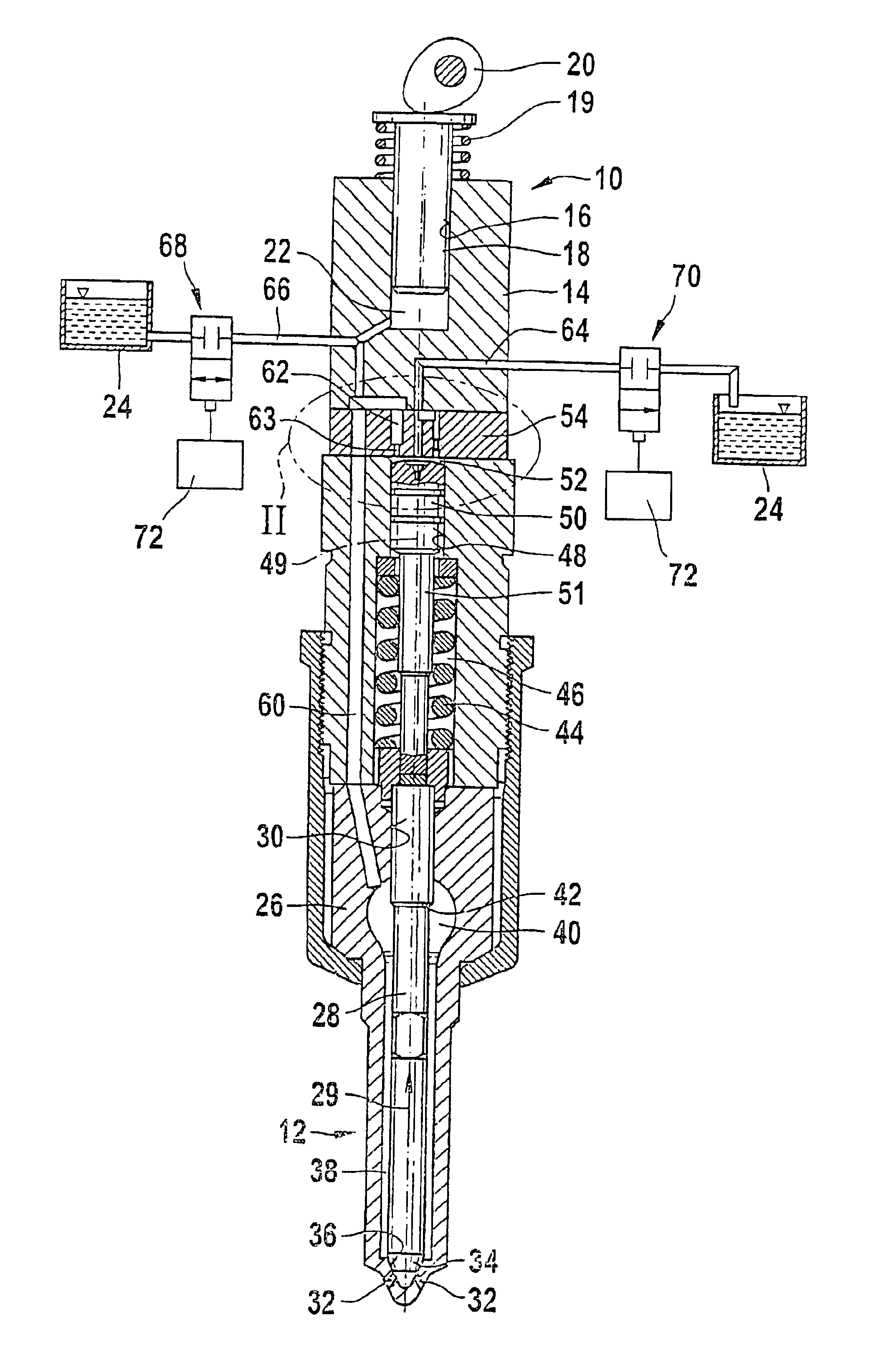
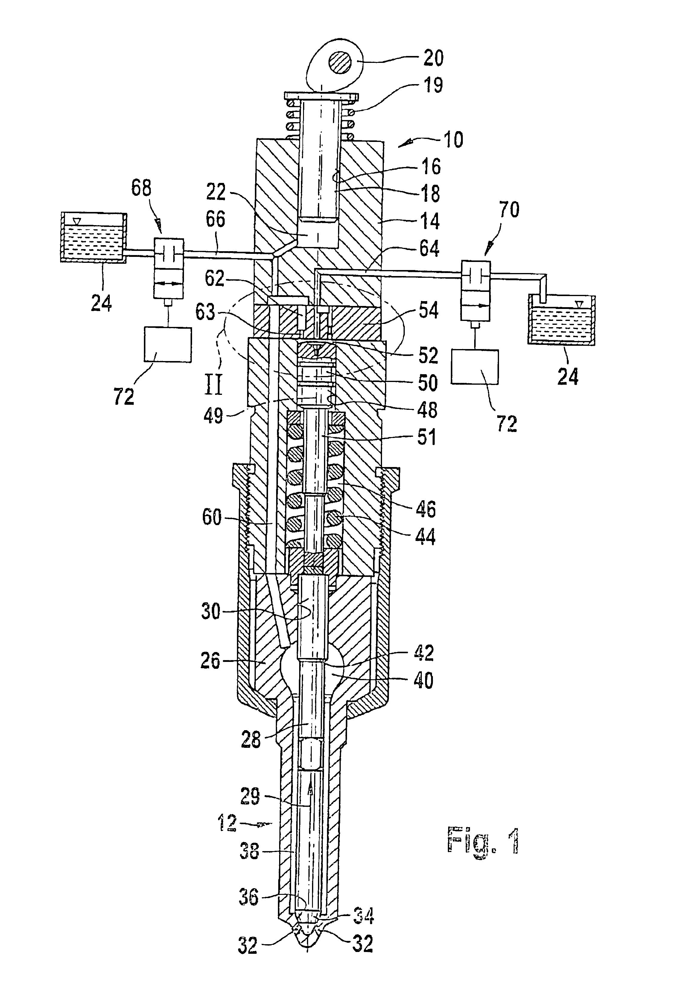
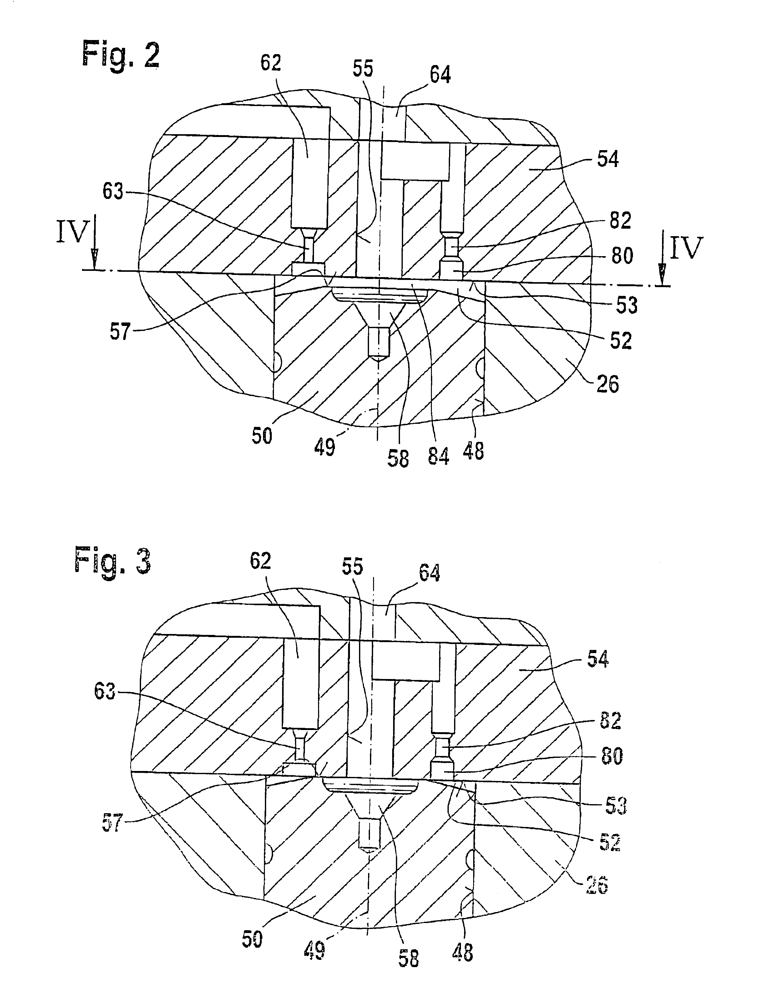
[0013]FIGS. 1 to 4 show a fuel injection apparatus for an internal combustion engine of a motor vehicle. The engine is preferably an internal combustion engine with autoignition. The fuel injection apparatus is preferably embodied as a so-called unit fuel injector and, for each cylinder of the engine, has a high-pressure fuel pump 10 and a fuel injection valve 12 connected to it, which comprise a common component. Alternatively, the fuel injection apparatus can also be embodied as a so-called unit pump system, in which the high-pressure fuel pump and the fuel injection valve of each cylinder are disposed separately from each other and are connected to each other via a line. The high-pressure fuel pump 10 has a pump body 14 with a cylinder bore 16 in which a pump piston 18 is guided in a sealed fashion, which piston is set into a stroke motion counter the force of a return spring 19, at least indirectly by means of a cam 20 of a camshaft of the engine. In the cylinder bore 16, the pu...


PUM


Abstract

There is disclose a high-pressure fuel pump and a fuel injection valve connected to it for each cylinder of an internal combustion engine. A pump piston of the pump delimits a working chamber connected to a pressure chamber of the injection valve having a valve element controlling injection openings and movable in an opening direction counter to closing force by pressure prevailing in the pressure chamber. A control valve controls connection of a control pressure chamber with the pump-working chamber delimited by a control piston to a relief chamber. When the injection valve element is closed, the control piston opens a main connection with a large flow cross section and when the injection valve element is open, this control piston closes the main connection, only opening a bypass connection with small flow cross section, the bypass connection is embodied in a housing part delimiting the control pressure chamber.

Description

CROSS-REFERENCE TO RELATED APPLICATIONS[0001]This application is a 35 USC 371 application of PCT / DE 02 / 04606 filed on Dec. 17, 2002.BACKGROUND OF THE INVENTION[0002]1. Art Field of the Invention[0003]The invention is directed to an improved fuel injection apparatus for an internal combustion engine,[0004]2. Description of the Prior Art[0005]A fuel injection apparatus of this kind is known from EP 0 987 431 A2. has a high-pressure fuel pump and a fuel injection valve connected to it for each cylinder of the internal combustion engine. The high-pressure fuel pump has a pump piston that delimits a pump working chamber and is driven into a stroke motion by the engine. The fuel injection valve has a pressure chamber connected to the pump working chamber and an injection valve element that controls at least one injection opening; the pressure prevailing in the pressure chamber can move the injection valve element in the opening direction counter to a closing force in order to open the at ...

Claims


Application Information

Patent Timeline
Patent Type & Authority Patents(United States)
IPC IPC(8): F02M61/00F02M61/20F02M57/00F02M57/02F02M59/36F02M59/20F02M47/02F02M63/00F02M47/00F02M51/00F02M61/10
CPCF02M47/027F02M57/023F02M59/366F02M61/205F02M2200/28F02M2200/16F02M2200/21
Inventor GRABANDT, PETER
Owner ROBERT BOSCH GMBH
Why Eureka
Try Eureka