Plastic paint container having a cube-shaped body

a plastic paint container and cube-shaped technology, applied in the field of containers, can solve the problems of difficulty in re-application or removal of the lid, small amounts of rust on the metal of the container, and falling into the paint in the container, etc., and achieve the effect of comprehensively addressing the foregoing and other deficiencies of conventional paint containers

Inactive Publication Date: 2005-05-24
THE SHERWIN-WILLIAMS CO
View PDF156 Cites 25 Cited by
  • Summary
  • Abstract
  • Description
  • Claims
  • Application Information

AI Technical Summary

Problems solved by technology

While the foregoing construction of a conventional paint container has benefits, it has drawbacks as well.
In addition, paint typically collects in the groove of the rim, which, when solidified, will cause difficulty in the re-application or removal of the lid at some later time.
Also, small amounts of rust often form on the metal of the container and then fall into the paint in the container.
For the most part, these efforts have failed to comprehensively address the foregoing and other deficiencies of conventional paint containers.

Method used


Image

  • Plastic paint container having a cube-shaped body
  • Plastic paint container having a cube-shaped body
  • Plastic paint container having a cube-shaped body

Examples


first embodiment

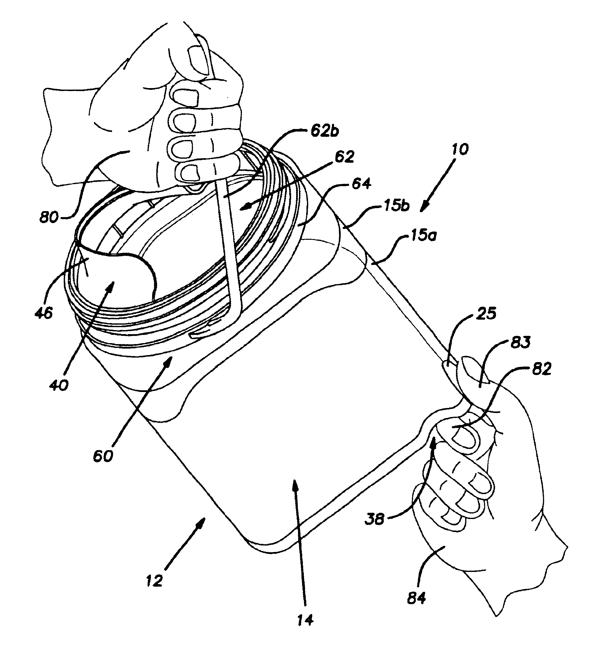
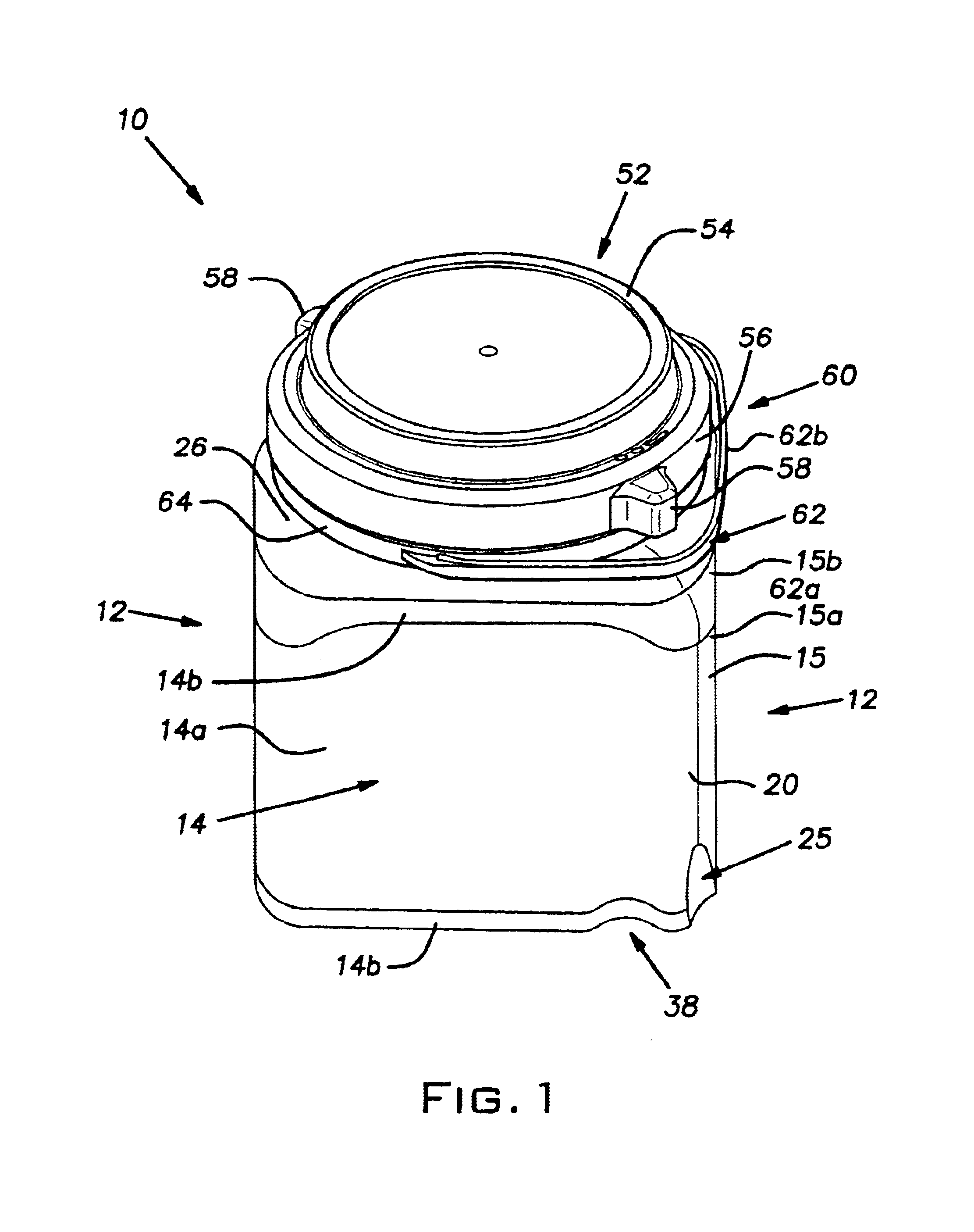
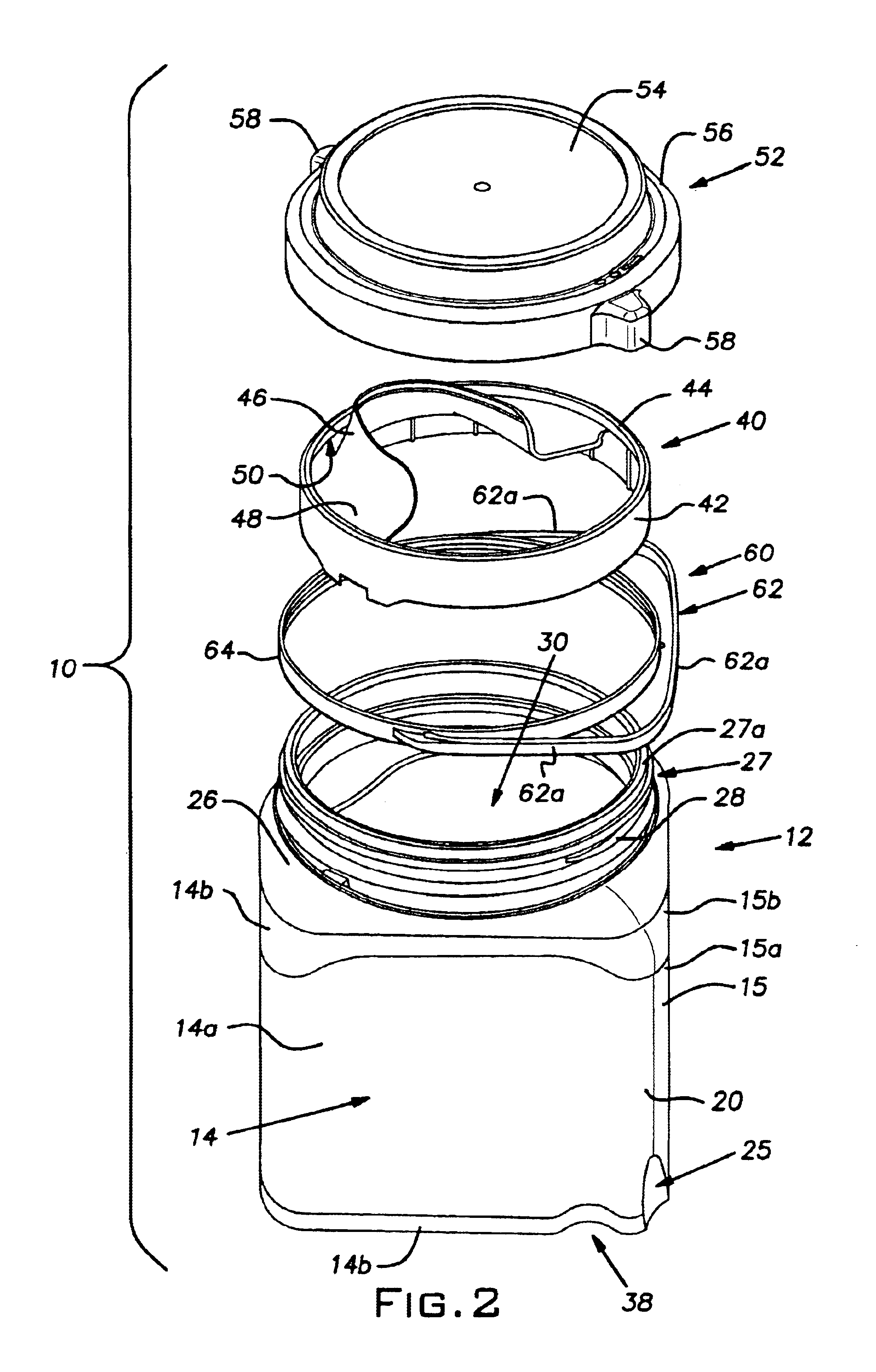
[0018]Referring now to FIGS. 1-3, there is shown a plastic paint container 10 constructed in accordance with the present invention. The container 10 is preferably blow molded from high density polyethylene and comprises a cube-shaped plastic body 12 having generally square side walls 14, 15, 16 and 17. The side walls 14-17 have a thickness of about 0.06 inches. The side walls 14 and 17 are joined at a rounded side corner 18 and the side walls 15 and 16 are joined at a rounded side corner 19. The side walls 14 and 15 are joined at a rear corner 20 and side walls 16 and 17 are joined at a sloping front corner 22. The side walls 14-17 respectively have planar central portions 14a, 15a, 16a, 17a disposed between rounded peripheral edge portions 14b, 15b, 16b, 17b. Although not shown, label(s) are secured to one or more of the central portions 14a, 15a, 16a, 17a. The peripheral edge portions 14b,15b, 16b,17b are raised above the central portions 14a, 15a, 16a, 17a so as to protect the la...

second embodiment

[0023]It should be appreciated that in lieu of the removable pouring insert 40, the container 10 may be blow molded with an integral pouring structure, such as the container 100 shown in FIG. 5, which is constructed in accordance with the present invention.

[0024]The lid 52 is tiered and comprises the cylindrical top portion 54, which is joined to a larger cylindrical bottom portion 56. The bottom portion 56 has an internal thread (not shown) for engaging the threads 28 of the collar 27 to threadably secure the lid 52 to the collar 27. A pair of grip tabs 58 extend radially outward from an outside surface of the bottom portion 56.

[0025]In one embodiment, the width of the container 10 is substantially the same as the diameter of a conventional cylindrical one gallon paint container, namely about 6⅝ inches. The height of the container 10, up to the top of the lid 52 (when it is securely threaded to the collar 27) is about 7⅞ inches. The interior volume of the container 10 is slightly g...


PUM


Abstract

A square paint container having recesses formed therein for facilitating the pouring of paint from the container.

Description

CROSS-REFERENCE TO RELATED APPLICATION[0001]This application claims the benefit of U.S. Provisional Application No. 60 / 394,095 filed Jul. 3, 2002, the entire disclosure of which is hereby incorporated by reference.BACKGROUND OF THE INVENTION[0002]The present invention relates to containers, more specifically to containers for holding viscous fluids, such as paint.[0003]Conventionally, paint is packaged in a cylindrical metal container having an upper rim with an annular groove formed therein that frictionally receives an annular protrusion of a lid for closing the container. If the container is a one gallon container, the container is typically provided with a wire bail handle connected to mounting ears secured to a side wall of the container. While the foregoing construction of a conventional paint container has benefits, it has drawbacks as well. A screw driver must be used to pry the lid off the paint container. In addition, paint typically collects in the groove of the rim, whic...

Claims


Application Information

Patent Timeline
Patent Type & Authority Patents(United States)
IPC IPC(8): B65D43/02B65D25/48B65D25/32B65D1/00B65D1/10B65D1/18B65D25/38B65D25/28B65D25/42B44D3/12
CPCB44D3/12B44D3/128B65D1/10B65D1/18B65D25/2897B65D25/32B65D25/48B65D43/0231B65D25/42B65D2543/00842B65D2543/00092B65D2543/00296B65D2543/00527B65D2543/00537
Inventor MCDONALD, ROBERT E.KATTERLE, PAUL R.KRAMER, JOHN F.
Owner THE SHERWIN-WILLIAMS CO
Why Eureka
Try Eureka