Air propelled water wad launcher

a technology of air-propelled water and launchers, which is applied in the direction of blow guns, white arms/cold weapons, weapons, etc., can solve the problems of known blowguns failing to reliably reload blowguns, and the feeding mechanism of many tendencies to jam

Inactive Publication Date: 2005-06-07
FORTI WILLIAM M +2
View PDF4 Cites 10 Cited by
  • Summary
  • Abstract
  • Description
  • Claims
  • Application Information

AI Technical Summary

Problems solved by technology

However, despite the relatively simple configurations of most, if not all of the known blowguns, the feeding mechanism often tends to jam due to incomplete automatic insertion of the next round.
Moreover, where the projectile is relatively soft or is soaked with a fluid, m...

Method used


Image

  • Air propelled water wad launcher
  • Air propelled water wad launcher

Examples


Embodiment Construction

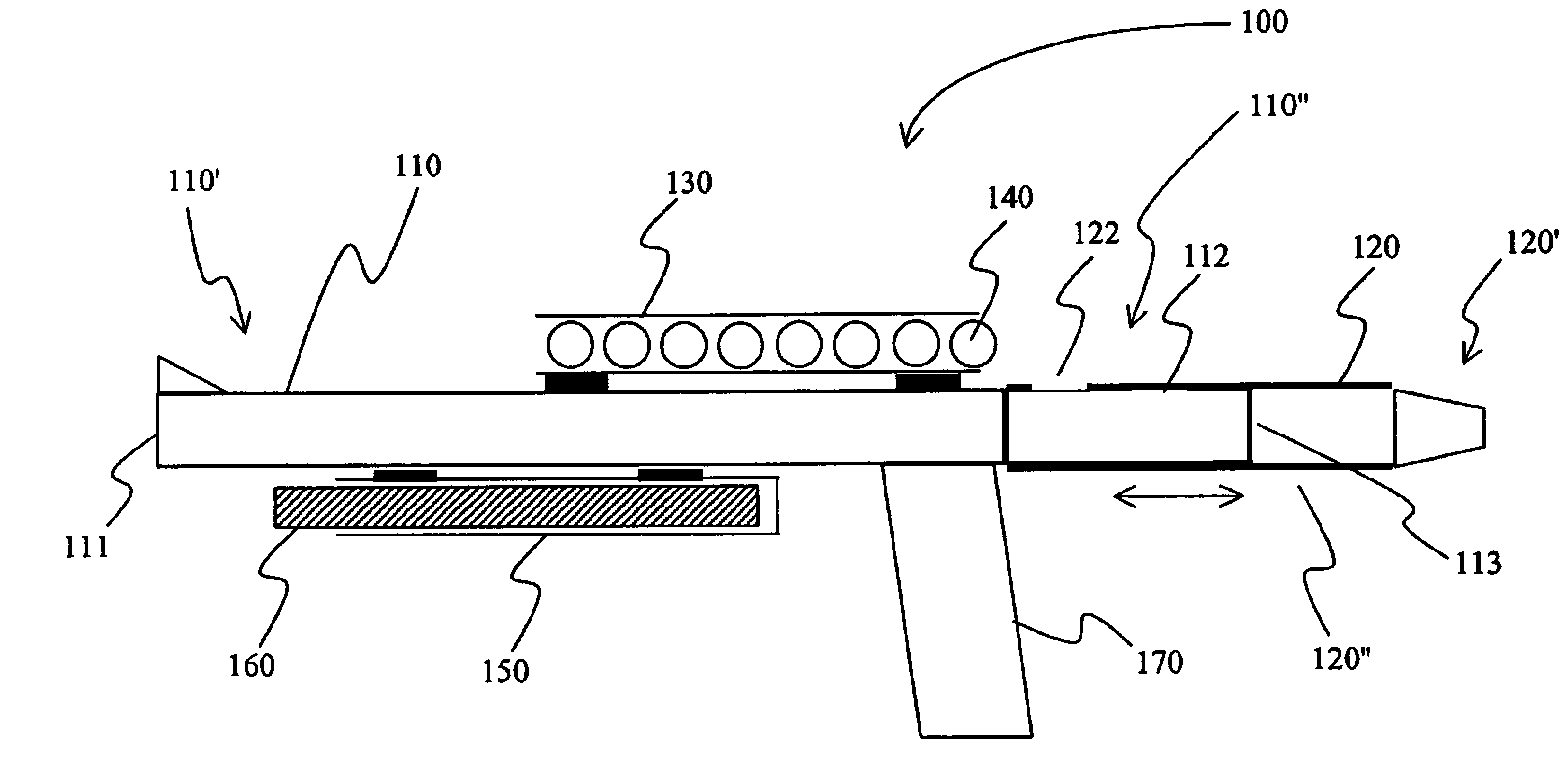
[0013]The inventors generally contemplate a toy in which fluid soaked soft projectiles are shot from a barrel by air blown through a mouthpiece, in which the fluid and the projectiles are carried on the toy, and in which the projectiles are loaded into the barrel through a continuous channel that is formed by a portion of the movable mouthpiece and a portion of the barrel.

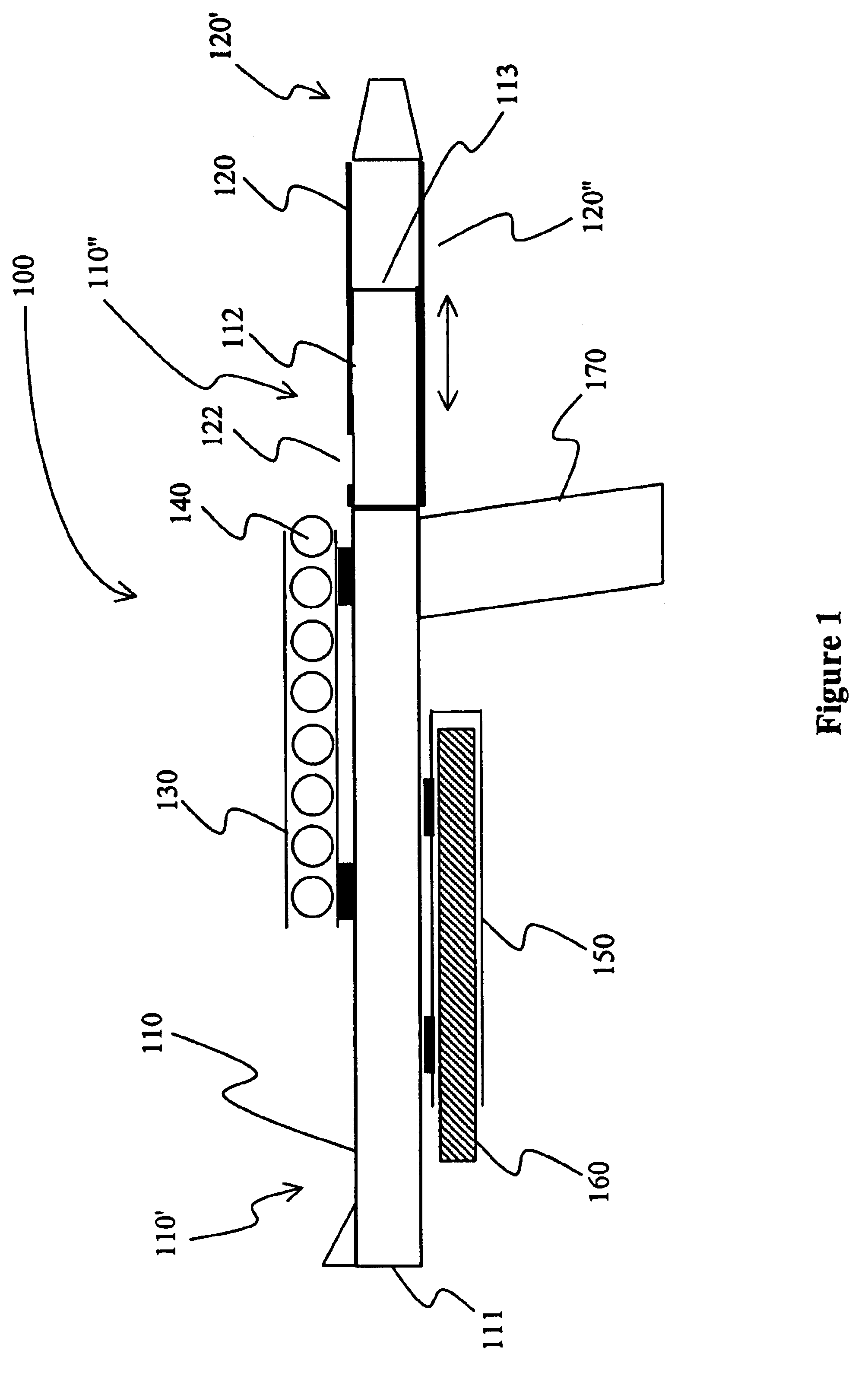
[0014]One exemplary blowgun is depicted in FIG. 1 in which blowgun 100 has a barrel 110 that is slidably coupled to a mouthpiece 120 such that the mouthpiece can move coaxial relative to the barrel (see double arrow). The barrel 110 has a proximal portion 110′ with a discharge opening 111 that corresponds to lumen of barrel, and a distal portion 110″ with a circular first opening 112 and a second opening 113 that corresponds to lumen of barrel. The mouthpiece 120 has one end 120′ that is configured to receive a blast of air from a user's mouth, and further has a circular load opening 122. The blast of air is then t...


PUM


Abstract

A blowgun has a movable mouthpiece coupled to a barrel, wherein a soft, and preferably fluid-soaked projectile is inserted into the barrel through the mouthpiece via a continuous channel that is formed by the mouthpiece and the barrel. After loading of the projectile, the channel is closed by moving the mouthpiece relative to the barrel.

Description

[0001]This application claims the benefit of our now abandoned U.S. provisional patent application with the Ser. No. 60 / 440,664, which was filed Jan. 15, 2003, and which is incorporated by reference herein.FIELD OF THE INVENTION[0002]The field of the invention is toy blowguns (U.S. Class 124 / 62).BACKGROUND OF THE INVENTION[0003]Air propelled toys enjoy increasing popularity, and particularly popular air propelled toys include blow guns, air propelled rockets, and paintball guns. Remarkably, while automation and launch power of most of such toys has considerably increased, devices and configurations for air propelled launchers using only the breath of a player (i.e., blowguns) remained relatively simple.[0004]A general depiction of a known blowgun is shown in U.S. Des. Pat. No. 358,444 to Bybee and a similar blowgun is further described in U.S. Pat. No. 4,419,978 to Loftus. In one improvement of a blowgun as described in U.S. Pat. No. 6,588,413 to Nagasue, the mouthpiece is configure...

Claims


Application Information

Patent Timeline
IPC IPC(8): F41B9/00F41B1/00
CPCF41B9/00F41B1/00
Inventor FORTI, WILLIAM M.FORTI, WILLIAM B.TURCHIK, DAVID M.
Owner FORTI WILLIAM M
Why Eureka
Try Eureka