
Offset tape measure

Inactive Publication Date: 2005-07-26
KLEIN TOOLS INC
View PDF17 Cites 19 Cited by
  • Summary
  • Abstract
  • Description
  • Claims
  • Application Information

AI Technical Summary

Problems solved by technology

This accordingly will affect the required labor to install the conductors, and ultimately affects the schedules and profits of the job.
The schedules and profits of the job are further affected by the labor and material costs involved in the installation of the conduit, and, as such, accurate measurements arc crucial.
Additionally, the installer must also consider that the conduit will shrink due to this detour.
Obviously, such a complete chart would hinder the installer at the job site, so smaller tables illustrating the most common offset angles are more commonplace.
In any event, this procedure, when used properly, is an adequate method for the offset bending of conduit runs, but it is often time consuming to refer to tables and make calculations as well as prone to error due to careless approximations.
Whenever a mistake is made installing conduit it costs money both in the form of labor and materials.
However, this method fails to incorporate easily readable pre-marked indicia that illustrate the correct distance between bends of known offset depths and angles.
However, these inventions fail to satisfy the niche required for precise determination of the distance between conduit tubing bends for all of the most commonly used offset angles quickly and precisely.

Method used


Image

  • Offset tape measure
  • Offset tape measure
  • Offset tape measure

Examples


Embodiment Construction

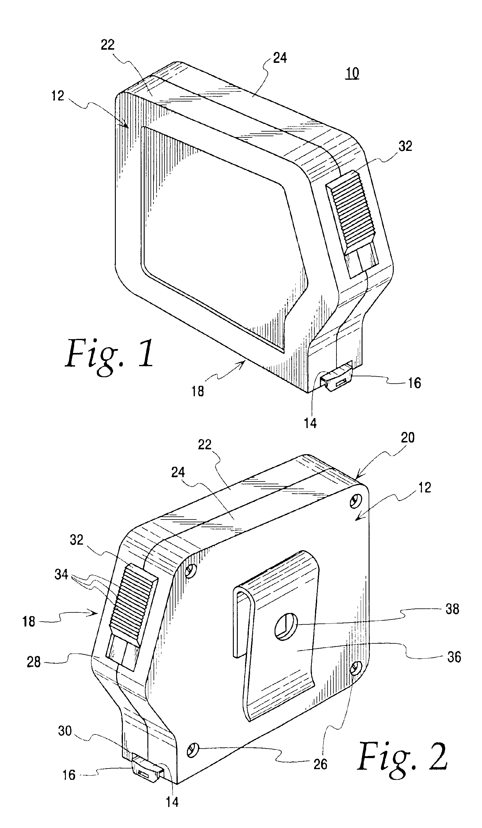
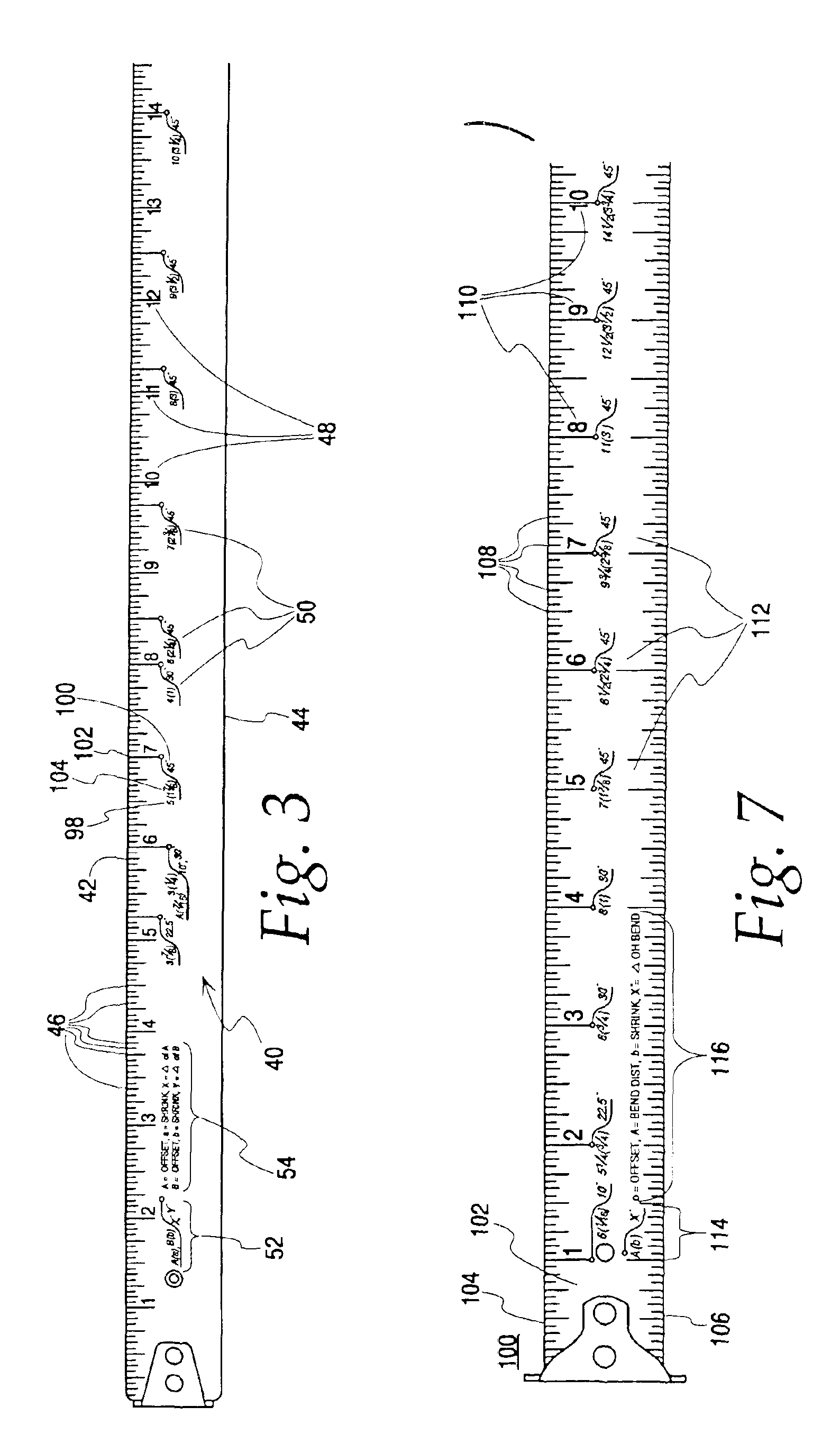
[0034]Referring now to the Figures, and in particular to FIGS. 1 and 2, a preferred embodiment of the offset tape measure embodying the principles and concepts of the present invention and generally designated by the reference numeral 10 will be described. Although the preferred embodiments will be described with respect to a retractable tape case, it will be appreciated that the present invention is applicable to any measuring device. For example, a folding rule, steel rule, wind-up flexible tape, wooden fixed rule, plastic fixed rule, markings on a level, or any other such markable device may be used. In any event, a preferred embodiment of the offset tape measure basically comprises a housing 12, a measuring tape 14 rolled and enclosed therein and a hook or flange member 16. More particularly, the housing 12 is formed in the conventional rectangular configuration with a front surface 18, a rear surface 20 and essentially hollow interior. The housing 12 is divided into front 22 an...


PUM


Abstract

An offset tape measuring tool marked with standard English measurements includes integrated indicia for quick determination of distance between bends for a given offset depth and offset angle when installing conduit. Additional indicia may be included for the measurement of the shrinkage of the conduit with respect to the specified offset depths and angles. The integrated invention may be part of a standard tape measure strip to provide a convenient multi-purpose tool. Although the tool eliminates any external calculations or table reference typically necessary when bending conduit to clear an obstacle, it still provides an optional reference card for unique bends.

Description

CROSS REFERENCE TO RELATED APPLICATION[0001]This application is a continuation-in-part, and, therefore, claims benefit under 35 U.S.C. § 120 of U.S. patent application Ser. No. 10 / 191,736, filed Jul. 9, 2002 now abandoned.BACKGROUND OF THE INVENTION[0002]The present invention relates generally to a measuring strip, and more particularly to a strip that may be used to measure offsets in rigid steel conduit, electrical metallic tubing, galvanized rigid conduit, rigid aluminum conduit and the like.[0003]When installing conduit to house runs of conductors, the installer inevitably will need to make bends in the conduit run in order to navigate around obstacles. Bends of various shapes are usually needed, such as right angle or 90-degree bends, offsets and saddles. Most, if not all, of these bends will be made on the job as part of the installation procedure and are, therefore, known as field bends.[0004]Before these field bends are actually made, it is essential that the installer do so...

Claims


Application Information

Patent Timeline
IPC IPC(8): B25H7/00G01B3/10G01B3/02
CPCB25H7/005G01B3/1084G01B3/1082G01B2003/1094G01B3/1003G01B3/1094
Inventor EKDAHL, KEVIN ALLENGOLDMANN, II, RUSSELL A.WONG, KINGSTON T.
Owner KLEIN TOOLS INC
Learn More