Supercharge Your Innovation With Domain-Expert AI Agents!

Method and apparatus for expandable liner hanger with bypass

a technology of expandable tubulars and bypasses, which is applied in the direction of drilling casings, drilling pipes, and accessories for wells, etc., can solve the problem of not being able to effectively use only partially expandable tubulars

Inactive Publication Date: 2005-07-26
WEATHERFORD TECH HLDG LLC
View PDF24 Cites 17 Cited by
  • Summary
  • Abstract
  • Description
  • Claims
  • Application Information

AI Technical Summary

Problems solved by technology

One problem with expandable tubular technology used with liners relates to cementing.
However, the tools for expanding tubulars are typically designed to expand the tubular in a circumferential fashion and cannot be effectively used to only partially expand the tubular.

Method used


Image

  • Method and apparatus for expandable liner hanger with bypass
  • Method and apparatus for expandable liner hanger with bypass
  • Method and apparatus for expandable liner hanger with bypass

Examples


Embodiment Construction

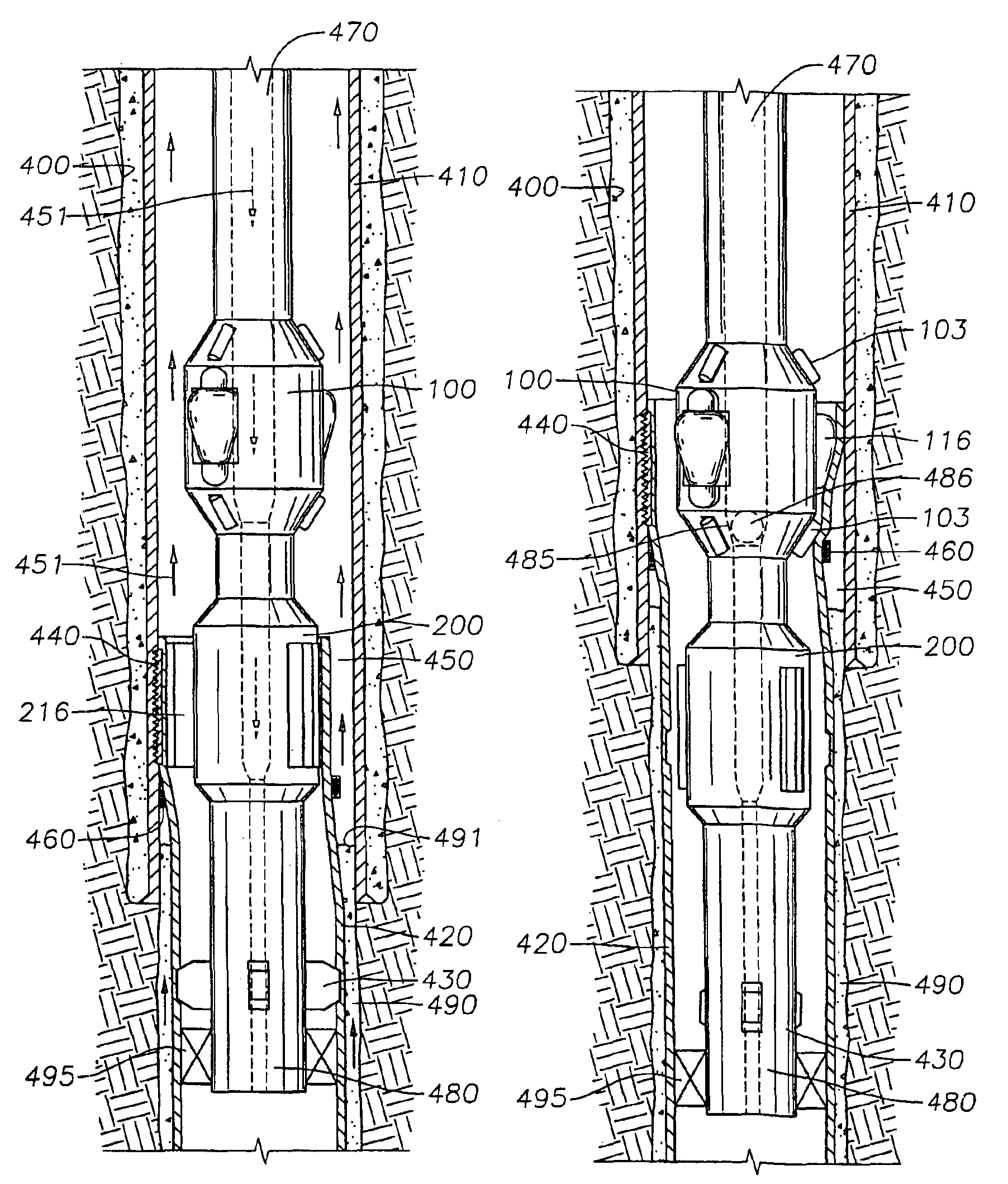
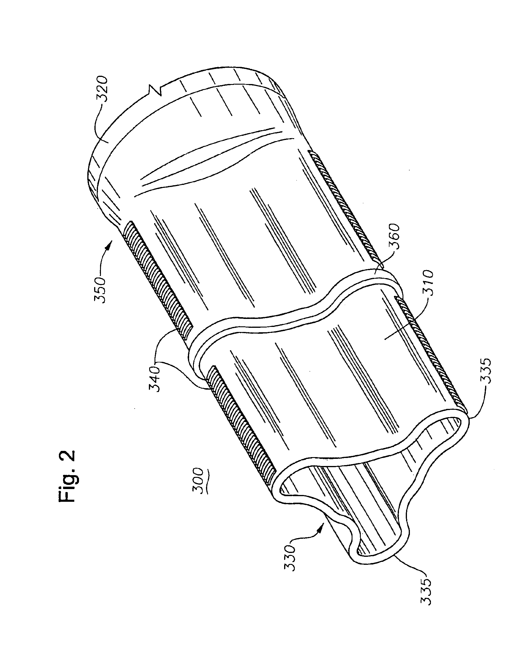
[0026]The present invention provides apparatus and method for setting a liner in a wellbore. FIG. 2 is a perspective view of a liner hanger 300 according to one embodiment of the invention. The liner hanger 300 has a generally tubular body 350 with an upper end 310 and a lower end 320. The upper end 310 has a maximum diameter smaller than the lower end 320 and is made of an expandable, ductile material. One or more slips 340 are formed on an outer diameter of the upper end 310 at a first location, or leg 335. The slips have grit or teeth on an outer surface thereof to help set the slips into the surrounding wellbore and hold the liner in place. Bypass areas 330 are formed between the legs 335 to permit a fluid path down the exterior of the liner. Preferably, three legs 435 are formed in the liner hanger 420 with a slip 440 formed on the outer diameter of each thereof. The liner hanger 300 is preformed into an irregular shape to create the bypass areas 330. The areas 330 may be any a...


PUM


Abstract

The present invention provides a liner hanger and a method of hanging a liner in a wellbore. In one aspect, a process for setting a liner in a wellbore is provided in which a tubular having a slip formed on an outer diameter of the tubular at a first location and a preformed bypass for circulating a fluid disposed at a second location is set and expanded into substantial contact with an inner diameter of the wellbore, a casing, or another liner. In another aspect, a process for setting a liner in a wellbore is provided in which a tubular having a slip formed on an outer diameter of the tubular at a first location is placed in the wellbore, a bypass for circulating a fluid is formed downhole, the liner is set and expanded into substantial contact with an inner diameter of the wellbore, a casing, or another liner. In yet another aspect, a process for creating a liner top seal is provided in which the liner is set by expanding a protrusion in an upper end of a tubular into substantial contact with an inner diameter of the wellbore, and the upper end of the tubular is then reformed and expanded into substantial contact with the inner diameter of the wellbore.

Description

CROSS-REFERENCE TO RELATED APPLICATIONS[0001]This application is a continuation of U.S. patent application Ser. No. 09 / 904,735 filed Jul. 13, 2001 now U.S. Pat. No. 6,648,075, and is herein incorporated by reference.BACKGROUND OF THE INVENTION[0002]1. Field of the Invention[0003]The invention relates to well drilling and completion, and to an apparatus and methods for use with expandable tubulars. Generally, the invention relates to a liner hanger and a method of hanging a liner.[0004]2. Background of the Related Art[0005]In the oil and gas exploration and production industry, bore holes are drilled in the earth to access hydrocarbon-bearing formations. The drilled bores are lined with steel tubing, known as casing or liner, which is cemented in the bore. After a certain depth is reached, drilling is halted and a well casing is lowered down the wellbore and cemented in place. Typically, drilling resumes in the wellbore until a next predetermined depth is reached. At this stage, dril...

Claims


Application Information

Patent Timeline
IPC IPC(8): E21B23/04E21B23/00E21B43/10E21B43/02E21B33/04E21B33/14
CPCE21B23/00E21B23/04E21B33/04E21B33/14E21B43/10E21B43/103E21B43/105E21B43/106
Inventor BADRAK, ROBERT P.COON, ROBERT J.SMITH, RODDIE R.MCGUIRE, PATRICK G.
Owner WEATHERFORD TECH HLDG LLC
Features
  • R&D
  • Intellectual Property
  • Life Sciences
  • Materials
  • Tech Scout
  • Unparalleled Data Quality
  • Higher Quality Content
  • 60% Fewer Hallucinations
Learn More