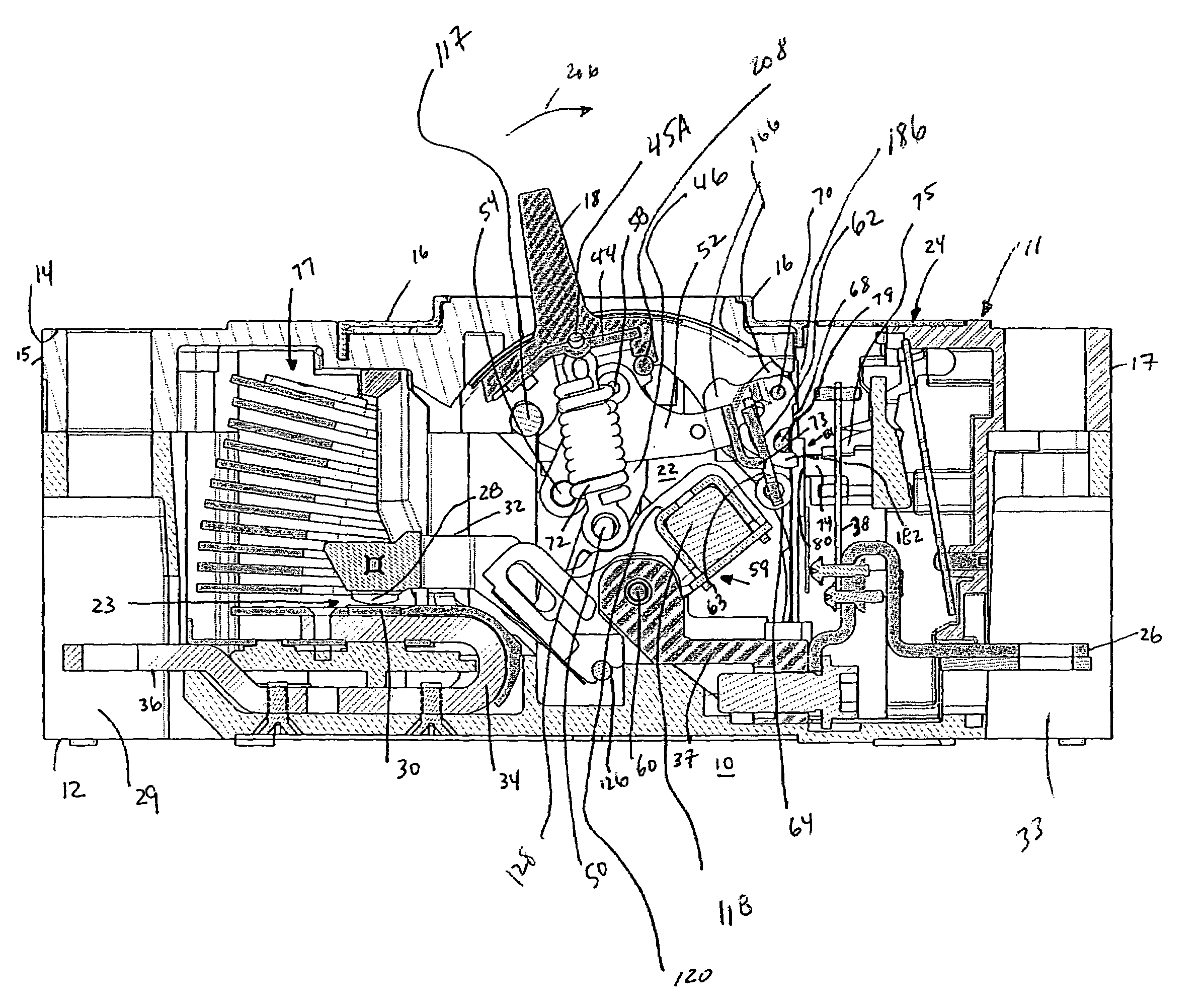
Circuit breaker including a latchable cradle and a cross bar adapted to move in an arcuate path away from primary and secondary latches
- Summary
- Abstract
- Description
- Claims
- Application Information
AI Technical Summary
Problems solved by technology
Method used
Image

Examples
Embodiment Construction
[0049]As employed herein, the term “bushing” means a removable or non-removable, cylindrical or non-cylindrical lining for an opening of one component, such as a side plate, employed to resist abrasion and / or to reduce friction with another component, such as the tab of a latch member.
[0050]As employed herein, the statement that two or more parts are “connected” or “coupled” together shall mean that the parts are joined together either directly or joined through one or more intermediate parts. Further, as employed herein, the statement that two or more parts are “attached” shall mean that the parts are joined together directly.
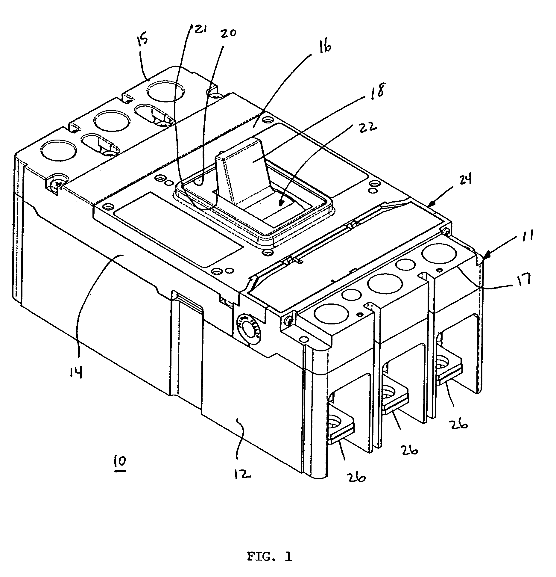
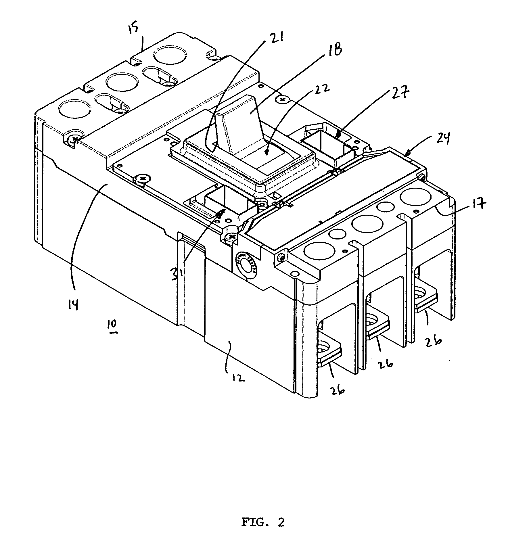
[0051]The present invention is described in association with a three-pole circuit breaker 10, although the invention is applicable to a wide range of circuit interrupters including one or more poles. Examples of circuit breakers are disclosed in U.S. Pat. Nos. 6,747,534 and 6,140,897, which are incorporated by reference herein.
[0052]Referring to FIGS. 1 and 2,...
PUM
 Abstract
Description
Claims
Application Information
 - R&D Engineer
- R&D Manager
- IP Professional
- Industry Leading Data Capabilities
- Powerful AI technology
- Patent DNA Extraction
Browse by: Latest US Patents, China's latest patents, Technical Efficacy Thesaurus, Application Domain, Technology Topic.
© 2024 PatSnap. All rights reserved.Legal|Privacy policy|Modern Slavery Act Transparency Statement|Sitemap