Bulk bag pallet tube apparatus

Inactive Publication Date: 2005-08-09
SCHNAARS JR DANIEL R +1
View PDF18 Cites 35 Cited by
  • Summary
  • Abstract
  • Description
  • Claims
  • Application Information

AI Technical Summary

Benefits of technology

[0016]It is a further object of the present invention to provide a bottom portion of the bag adapted with rigid members for defining a level, secure means to both transport the filled bag and allow the bag to be safely stacked on other such bulk filled bags.
[0017]It is a further object of the present invention to provide support members insertable into sleeves on the bottom of a bulk bag which allows the support members to contact the surface upon which the bag rests without contacting the sleeves.
[0018]It is a further object of the present invention to provide rigid inserts for bulk bags made of high density polyethylene which can be injection molded rather than extruded plastic, to allow for geometric shaping of the insert and to use a variety of plastic materia

Problems solved by technology

Lifting loops are difficult to access by a forklift and usually takes a second person to assist.
Pallets, although easily accessible, are usually made of wood, and over time will be susceptible to splintering, mold, or insects.
Plastic pallets may eliminate these problems, but are very expensive to produce.
One problem with transporting and storing bags of this type is that the bags, in order to conserve space, would typically be stacked upon one another to a height, so long as the bags did not risk of toppling over.
However, because of the soft underside of the bags, when the bags, filled with dry, powdery bulk, are stacked upon one another, the bulk within the bag may shift, and in doing so, may cause the bag to lose its center of gravity and fall from its resting place,

Method used


Image

  • Bulk bag pallet tube apparatus
  • Bulk bag pallet tube apparatus
  • Bulk bag pallet tube apparatus

Examples


Example

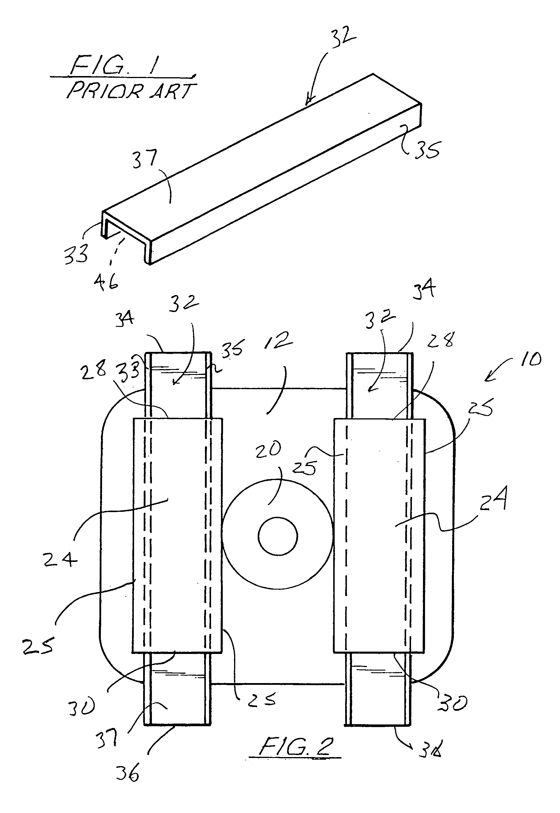
[0031]FIG. 1 illustrates a generally three-sided insert 32 which is known in the art, insertable into sleeves formed on the lower end of a fabric bulk bag, the insert 32 including an upper wall 37 with two side walls 33, 35 formed along its length. This insert would be a very basic insert which would not include any of the improvements as will be discussed in relation to the present invention.

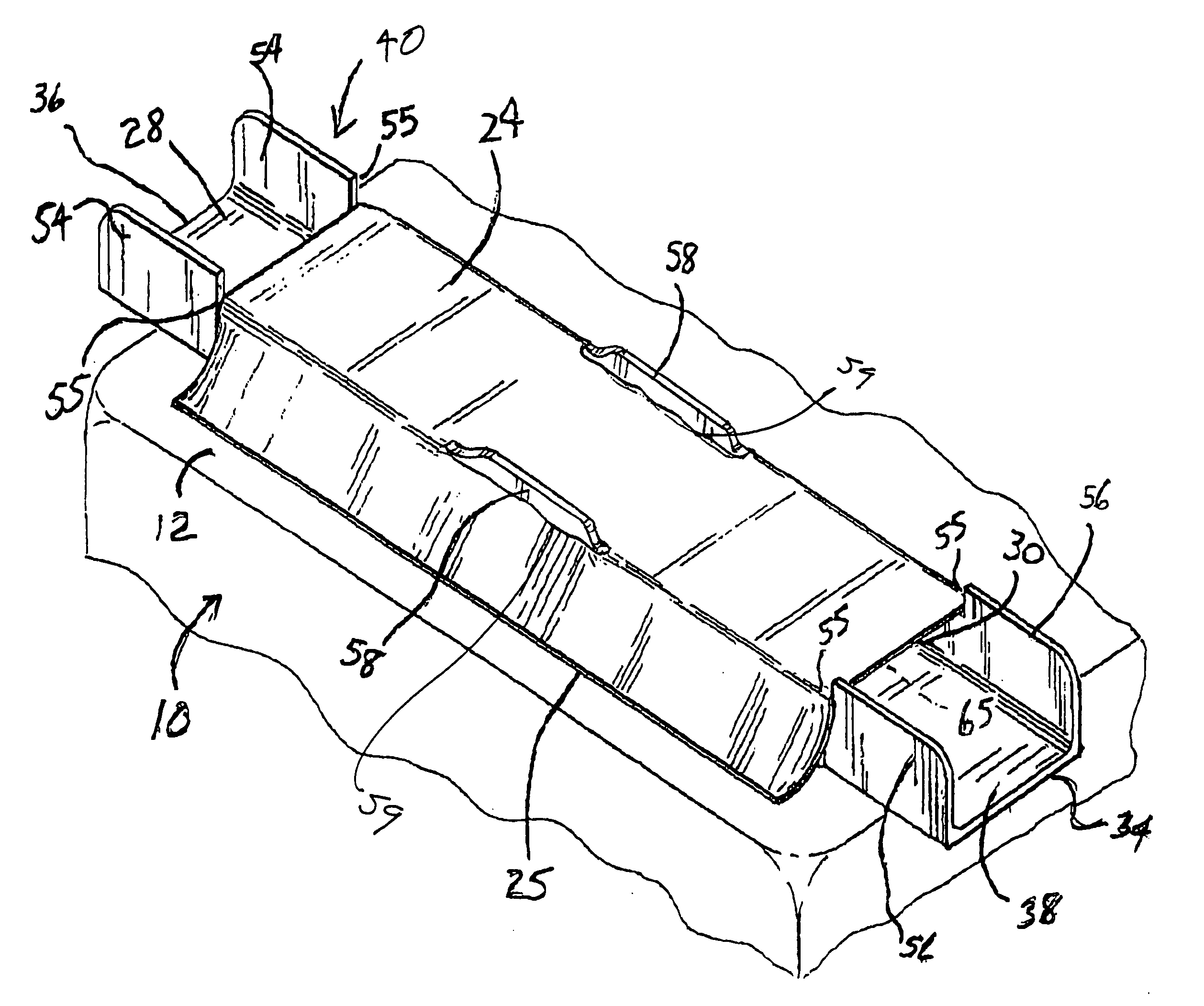
[0032]As illustrated in FIG. 2, there is illustrated the underside 12 of a bulk bag 10, of the type having a top wall 14, side walls 16, which are illustrated more fully in FIGS. 7 and 8. In most cases the bulk bag 10 would have an opening in its top wall through which bulk material is poured into the bag space 18, and an opening 20 on its underside 12 for allowing the bulk to flow from the bag space 18, when the normally closed opening 20 is opened. The opening 20 would usually include a down spout for allowing the bulk material to flow into another vessel or the like. These features are quite...


PUM


Abstract

An improved fabric bulk bag, of the type having wall portions, a top portion, and a floor portion, all defining a space for storing bulk therein, and further providing a pair of channels, substantially parallel in relation, secured along the outer surface of the floor portion, each channel having two open ends; a substantially elongated rigid U-shaped support member insertable into each channel, the upper wall of the member contacting the outer surface of the bulk bag, and the two arms of the U-shaped member providing a travel space through the channel for receiving the tynes of a forklift, and allowing the tynes to contact the upper wall of the member when the bag is lifted; the two arms of the member also providing a stable pallet-like foundation for the bag when the bag is positioned atop another filled bag. There is further provided finger-like openings between the walls of the U-shaped member and the channels, to secure the edges of each channel to maintain the U-shaped member within each channel when the forklift tynes are engaging or disengaging from the channels. There is further provided blocks along the outer walls of the channel walls for filling any gaps between the fabric channels and the U-shaped members inserted therein.

Description

CROSS-REFERENCE TO RELATED APPLICATIONS[0001]Not applicableSTATEMENT REGARDING FEDERALLY SPONSORED RESEARCH OR DEVELOPMENT[0002]Not applicableREFERENCE TO A “MICROFICHE APPENDIX”[0003]Not applicableBACKGROUND OF THE INVENTION[0004]1. Field of the Invention[0005]The apparatus of the present invention relates to fabric bulk bags. More particularly, the present invention relates to a bulk bag having a floor portion which includes a pair of spaced apart pockets for receiving a rigid member to define a channel through which tynes of a forklift may enter, for lifting the bag, and the rigid members being maintained in the pockets for defining a flat surface for the bag to rest upon the floor or other bags.[0006]2. General Background of the Invention[0007]Bulk bags are for the most part bags constructed of a polypropylene material which would normally be of the type having four side walls, a bottom wall, a top wall and means such as loops for lifting the bag with a forklift after the bag ha...

Claims


Application Information

Patent Timeline
IPC IPC(8): B65D19/00B65D88/16
CPCB65D88/1687B65D2588/167
Inventor SCHNAARS, JR., DANIEL R.SCHNAARS, MATTHEW D.
Owner SCHNAARS JR DANIEL R
Why Eureka
Try Eureka