
Golf club head

Inactive Publication Date: 2005-08-09
DAIWA SEIKO CORPORATION
View PDF14 Cites 68 Cited by
  • Summary
  • Abstract
  • Description
  • Claims
  • Application Information

AI Technical Summary

Benefits of technology

[0024]The constructed golf club head incorporates the shaft securing portion which is firmly supported by a top portion of and

Problems solved by technology

However, the cast golf club head incorporating the shaft securing portion and the head body molded integrally with each other, suffers from the following problem: the molding material is usually accumulated in between the shaft securing portion and the heel wall of the head body during the manufacturing process.
Therefore, the manufactured head encounters excessive enlargement of the thickness of the portion in the vicinity of the shaft securing portion because the shaft securing portion is integrated with the heel wall.
Hence it follows that the weight of the heel portion is enlarged, causing the balance of weight to deteriorate.
If the shaft securing pipe is welded insufficiently, there is apprehension that the welded portion is broken owing to an impact.
Since a plurality of the members, such as the top member, the face member, the shaft securing pipe and the bottom member, are welded when the golf club head is manufactured, there arises a point-out problem in that greater manhours and cost are required as compared with the forged head.
There arises another problem in that a satisfactorily large area for bonding the shaft (not shown) cannot be obtained.
Moreover, a satisfactory area for bonding the shaft cannot be obtained.
However, whether or not the foregoing general structure molded by casting has not been disclosed.
In addition, no description has been made about the structure, operation and the effect of the structure.
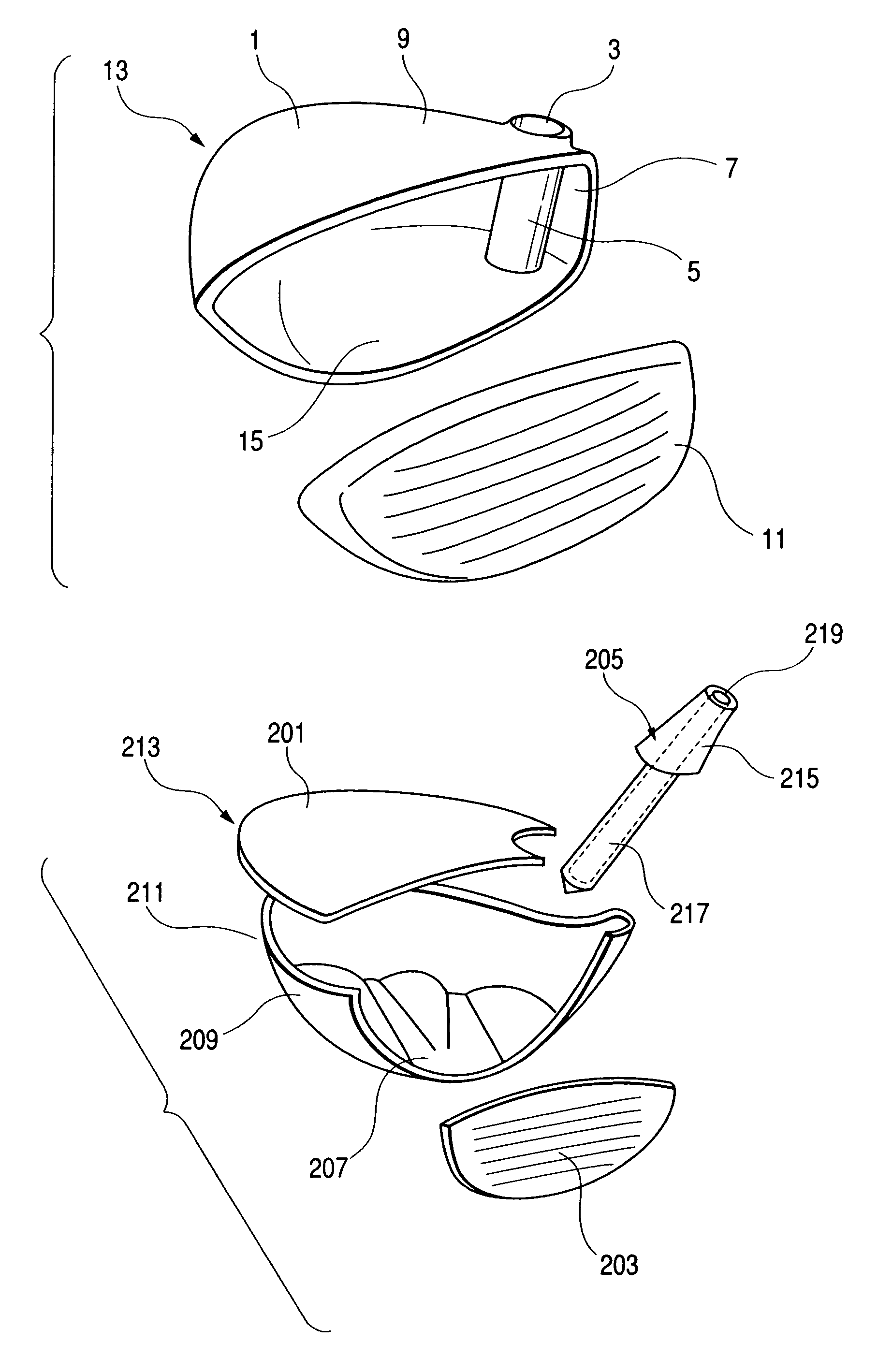
However, there arises a pointed-out problem in that great manhours and cost are required to manufacture the golf club head because the plural elements, such as the top member 201, the face member 203, the neck member 205 and the bottom member 211, are welded to one another.
If the foregoing elements are welded insufficiently, there is apprehension that the welded portion is broken owing to an impact.
There arises another problem in that use of the individual neck member 205 inhibits reliably large strength of the shaft securing portion.
Thus, there arises a problem in that the weight of the heel portion is enlarged, causing the balance of weight of the head to deteriorate.

Method used


Image

  • Golf club head
  • Golf club head
  • Golf club head

Examples


second embodiment

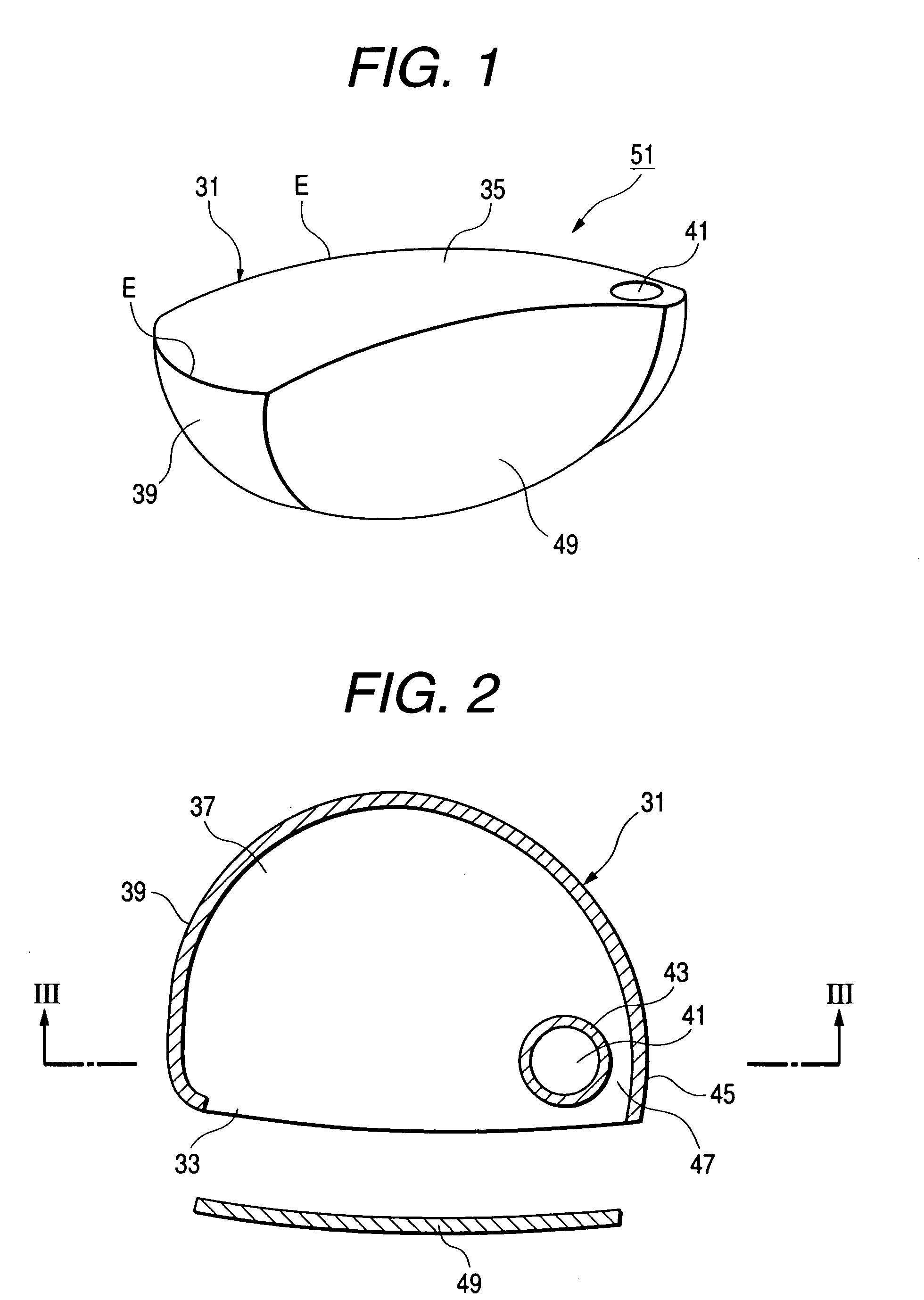
[0087]FIGS. 8 to 10 are diagrams showing a head manufactured by a manufacturing method according to a Referring to FIGS. 8 to 10, reference numeral 221 represents a head body constituted by a hollow outer shell made of a metal material, such as a titanium alloy, and incorporating a top portion 225, a face portion 227 and a side portion 229 which are integrally molded with one another except for a sole-side opening 223. A heel portion of the head body 221 incorporates a cylindrical shaft securing portion (a hosel portion) 233 in which a shaft securing hole 231 in the form of a through hole is formed from the top portion 225 to the sole-side opening 223. A hollow portion 47 is formed between the shaft securing portion 233 and the heel wall 234 of the head body 221 such that a predetermined clearance is created.

[0088]The upper end of the shaft securing portion 233 is lower than the apex of the top portion 225 (the highest portion of the top portion 225 when addressing is performed).

[0...

third embodiment

[0103]FIG. 12 shows a Although the foregoing embodiment is structured such that the projecting mold member 257 is integrally molded with the lower mold 243. This embodiment is structured to produce the split pattern to manufacture the head body such that a mold member 257-1 having the same shape as that of the mold member 257 is molded by using ceramics such that the mold member 257-1 is individual from the lower mold 243-1.

[0104]The other split patterns for molding the wax mold are similar to those according to the foregoing embodiment. Therefore, the same elements are given the same reference numerals.

[0105]A manufacturing method according to this embodiment will now be described. Initially, as shown in FIG. 12, the cores 247, 249 and 251 and the pin 255 are joined to the inside portion of the cavity 245 constituted by the upper mold 241 and the lower mold 243-1. Moreover, a mold member 257-1 is disposed in a heel portion adjacent to the pin 255. Then, the split patterns are join...

fourth embodiment

[0117]FIGS. 13 and 15 are diagrams showing a head manufactured by a method according to a Referring to FIGS. 13 to 15, reference numeral 261 represents a head body constituted by a hollow outer shell obtained by integrally casting a top portion 265, a sole portion 267 and a side portion 269 with a metal material, such as a titanium alloy, except for a face-side opening 263. The heel portion of the head body 261 has an extracting hole 275 through which mold members 271 and 273 to be described later are extracted. A forged or cast plate 277 is welded to close the extracting hole 275. The plate 277 and the heel member 264 molded integrally with the head body 261 constitute the heel wall of the head body 261.

[0118]As shown in FIG. 15, the heel portion of the head body 261 has a cylindrical shaft securing portion 281 in which a shaft securing hole 279 is formed from the top portion 265 to the sole portion 267 and which is integrally molded between the top portion 265 and the sole portio...


PUM


Abstract

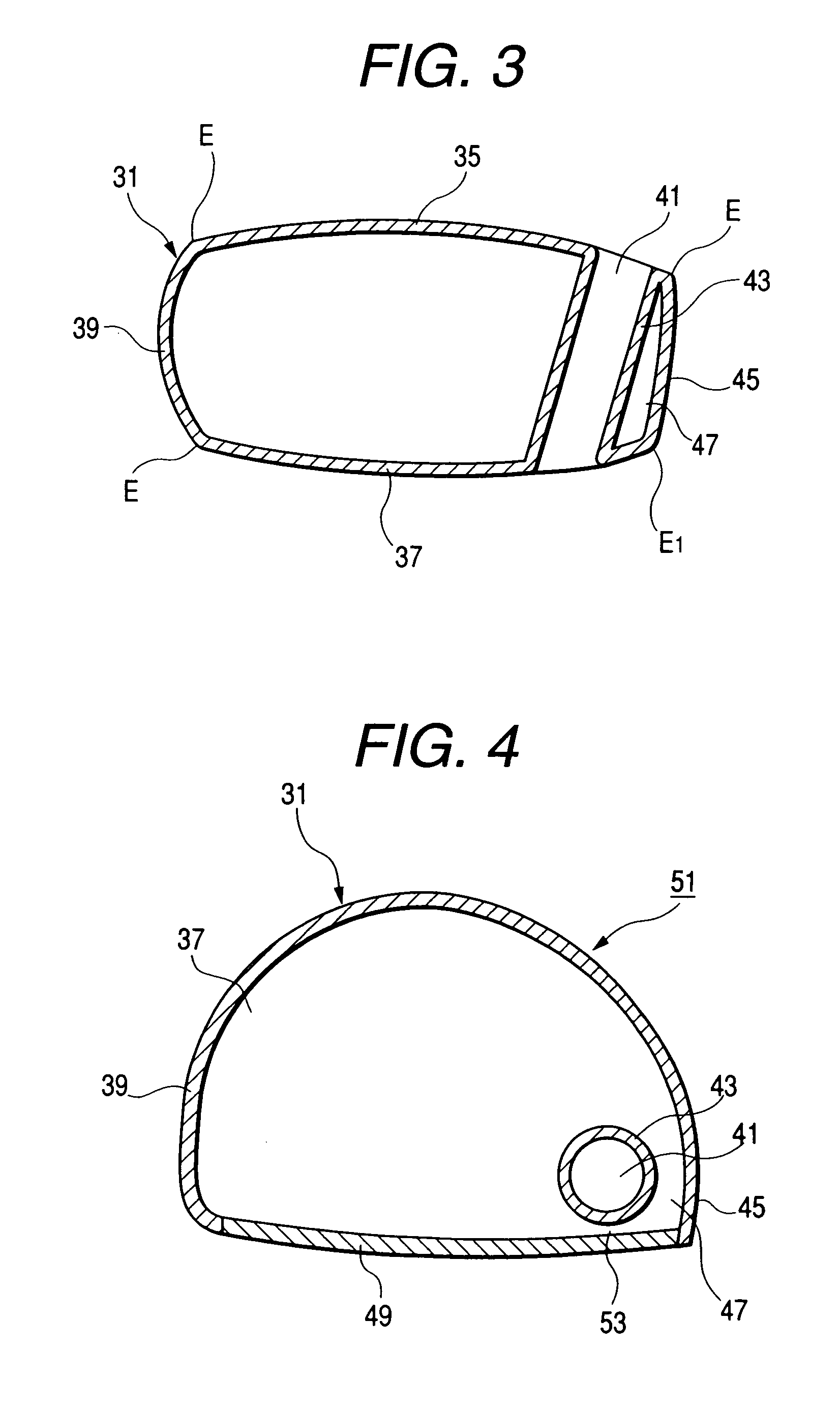
A golf club head of the present invention. A cast head body 31 is constituted by a hollow outer shell. Said hollow outer shell define a top portion 35, a sole portion 37, a heel wall 45, a toe portion 39 and a face opening portion 33. A shaft securing portion 43 is formed adjacent to the heel wall and extended from the top portion to the sole portion. And a first hollow portion 47 is formed between the shaft securing portion and the heel wall of the head body.

Description

BACKGROUND OF THE INVENTION[0001]The present invention relates to a golf club head having a structure that the strength of a shaft securing portion for securing a shaft to the body of the club head is increased and the balance of weight is improved and a manufacturing method therefor.[0002]In recent years, the head bodies of golf club heads (hereinafter called “heads”) of golf clubs called the “woods” have widely been used, the head bodies each incorporating a hollow outer shell made of a metal material, such as titanium or stainless steel. The metal material is employed as a substitute for a general natural wood, such as a persimmon tree or a cherry tree, from viewpoints of stability of the quality and easiness of material acquisition.[0003]Hitherto, a method of manufacturing a head of the foregoing type has been known which is arranged as shown in FIGS. 29 and 30. That is, a metal material, such as titanium, is used to mold a top member 201, a face member 203, a neck member 205 an...

Claims


Application Information

Patent Timeline
IPC IPC(8): A63B53/04A63B53/02
CPCA63B53/02A63B53/0466A63B2053/0408A63B2209/00A63B2053/0416A63B53/0408A63B53/0416A63B60/00
Inventor KUSUMOTO, HARUNOBUSASAMOTO, AKINORI
Owner DAIWA SEIKO CORPORATION
Learn More