Eureka AIR delivers breakthrough ideas for toughest innovation challenges, trusted by R&D personnel around the world.

Modular orthopaedic implant apparatus and method

a technology of orthopaedic implants and modularity, applied in the field of prosthetic orthopaedic implants, can solve the problems of requiring the outer shell to have a wide range of thicknesses, requiring the use of final outer shell components in the trial reduction of joints, and expensive and inconvenient manipulation in the surgical environmen

Inactive Publication Date: 2005-08-09
DEPUY PROD INC
View PDF29 Cites 71 Cited by
  • Summary
  • Abstract
  • Description
  • Claims
  • Application Information

AI Technical Summary

Benefits of technology

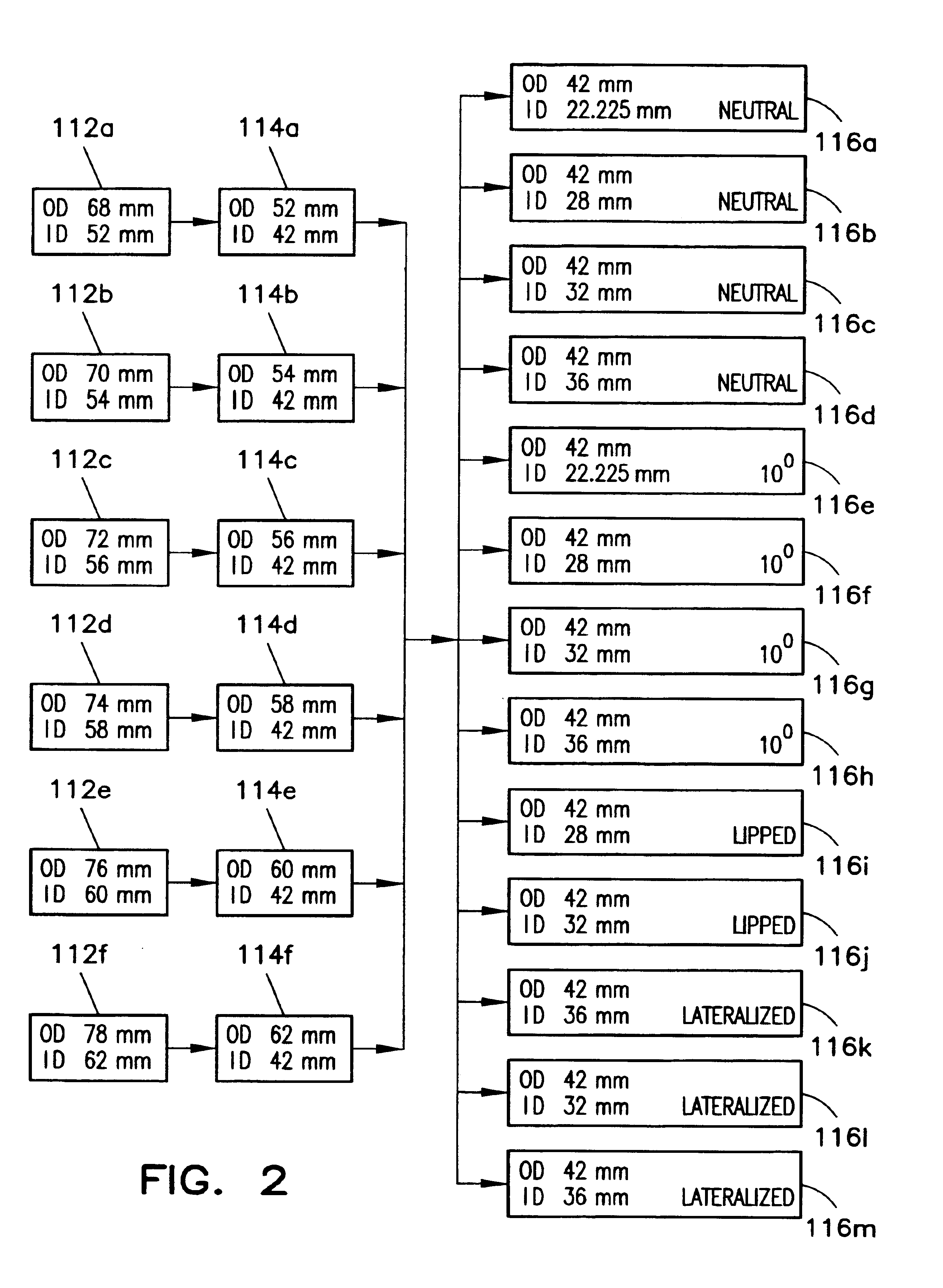
The present invention provides a trial acetabular kit and method that uses multiple intermediate spacers to allow for a single set of inner liners to be used with multiple sizes of outer shell components. This results in a more uniform and consistent thickness of the outer shell, making it easier to achieve the same dimensions as the final outer shell.

Problems solved by technology

The technical problem addressed in this patent is how to create a modular acetabular trial system and method that allows for flexible selection of outer shell sizes and inner liner styles without requiring a large amount of trial components. This reduces costs and makes managing the inventory easier for surgeons.

Method used


Image

  • Modular orthopaedic implant apparatus and method
  • Modular orthopaedic implant apparatus and method
  • Modular orthopaedic implant apparatus and method

Examples


Embodiment Construction

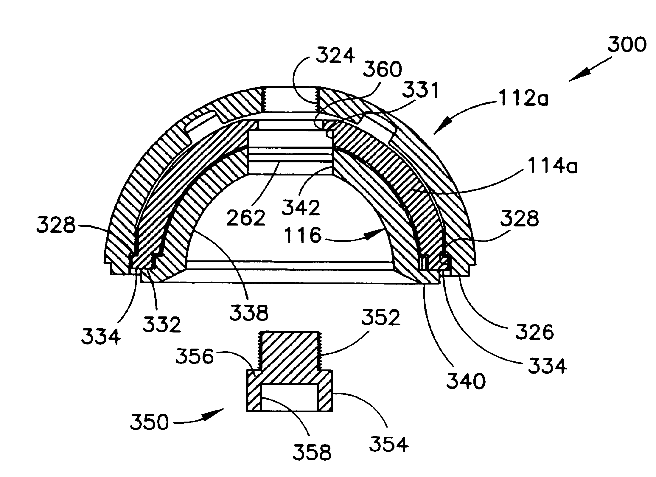
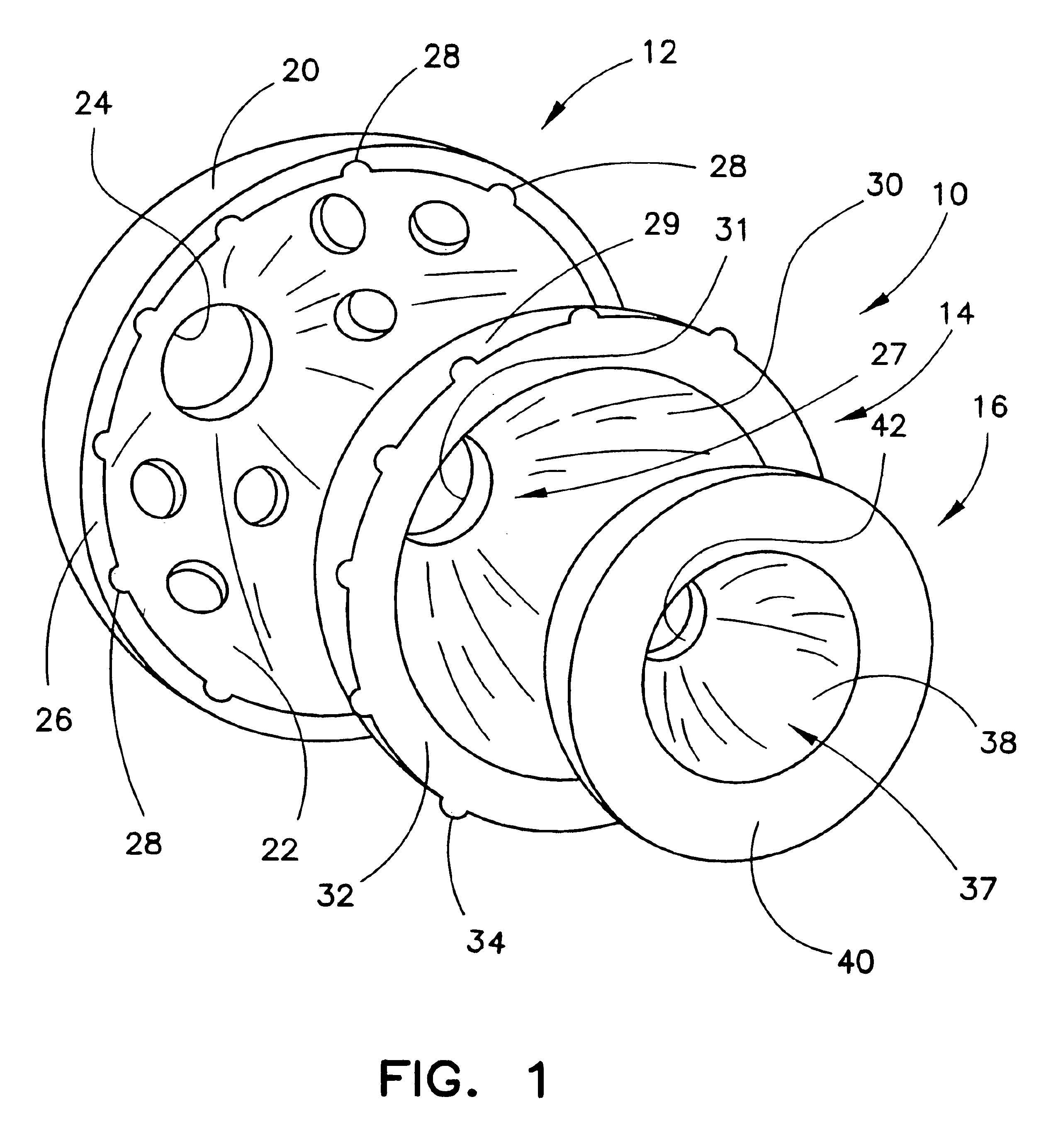
[0027]FIG. 1 shows an exploded perspective view of an exemplary modular acetabular trial 10 according to the present invention. The modular acetabular trial 10 is generally configured to be received in the acetabulum of a patient. The modular acetabular trial 10 is further configured to receive a femoral head, not shown, but which would be known in the art.

[0028]The components of the modular acetabular trial 10 are used, in whole or in part, as trial implants to ascertain the appropriate size and style of acetabular cup that will be finally implanted. In particular, the surgeon may use the components of the modular acetabular trial 10, either as a unit or as subcombinations, to determine the outer shell diameter and the inner liner style of the final acetabular cup implant.

[0029]The modular acetabular trial 10 includes an outer shell 12, an intermediate component 14 and an inner liner component 16. The outer shell 12 includes a rounded outer surface 20, which is substantially hemisp...


PUM


Abstract

A trial implant kit includes a plurality of intermediate components and a plurality of inner components. Each of the plurality of intermediate components has a uniform inner surface, although at least two of the plurality of intermediate components having distinct outer surfaces. Each of the distinct outer surfaces is configured to engage one of a plurality of acetabular shell component geometries. Each of the plurality of inner components has a uniform outer surface portion and a bearing surface, the uniform outer surface portion configured to be received by the uniform inner surface of any of plurality of intermediate components. The bearing surface is configured to engage a femoral head. At least two of plurality of inner components having distinct bearing surface configurations.

Description


Claims


Application Information

Patent Timeline
Owner DEPUY PROD INC
Why Eureka
Eureka Blog
Learn More