Method and apparatus for delivering an agent

a technology of delivering an agent and a method, which is applied in the field of bone fixation devices and medical agents, can solve the problems of introducing several significant problems, and affecting the treatment effect of patients,

Inactive Publication Date: 2006-04-27
INTERVENTIONAL SPINE
View PDF99 Cites 72 Cited by
  • Summary
  • Abstract
  • Description
  • Claims
  • Application Information

AI Technical Summary

Problems solved by technology

However, portions of the femur are extremely susceptible to fracturing.
Fractures of the femur which extend into the neck of the bone are generally more difficult to treat than fractures restricted to the shaft of the femur.
The leading end portion of the implant typically includes means to positively grip the femoral head bone (external threads, expanding arms, etc.), but the inclusion of such gripping means can introduce several significant problems.
First, implants with sharp edges on the leading end portion, such as the externally threaded implants, exhibit a tendency to migrate proximally towards the hip joint weight bearing surface after implantation.
This can occur when the proximal cortical bone has insufficient integrity to resist distal movement of the screw head.
Such proximal migration under physiological loading, which is also referred to as femoral head cut-out, can lead to significant damage to the adjacent hip joint.
Also, the externally threaded implants can generate large stress concentrations in the bone during implantation which can lead to stripping of the threads formed in the bone and thus a weakened grip.
As a result, all fatigue loading is concentrated at the attached ends of the arms and undesirably large bending moments are realized at the points of attachment.
In addition, conventional threaded implants generally exhibit insufficient holding power under tension, such that the threads can be stripped out of the femoral head either by overtightening during the implantation procedure or during post operative loading by the patient's weight.
However, these devices and methods are unsatisfactory as they may involve complicated devices and methods of delivery.

Method used


Image

  • Method and apparatus for delivering an agent
  • Method and apparatus for delivering an agent
  • Method and apparatus for delivering an agent

Examples


Embodiment Construction

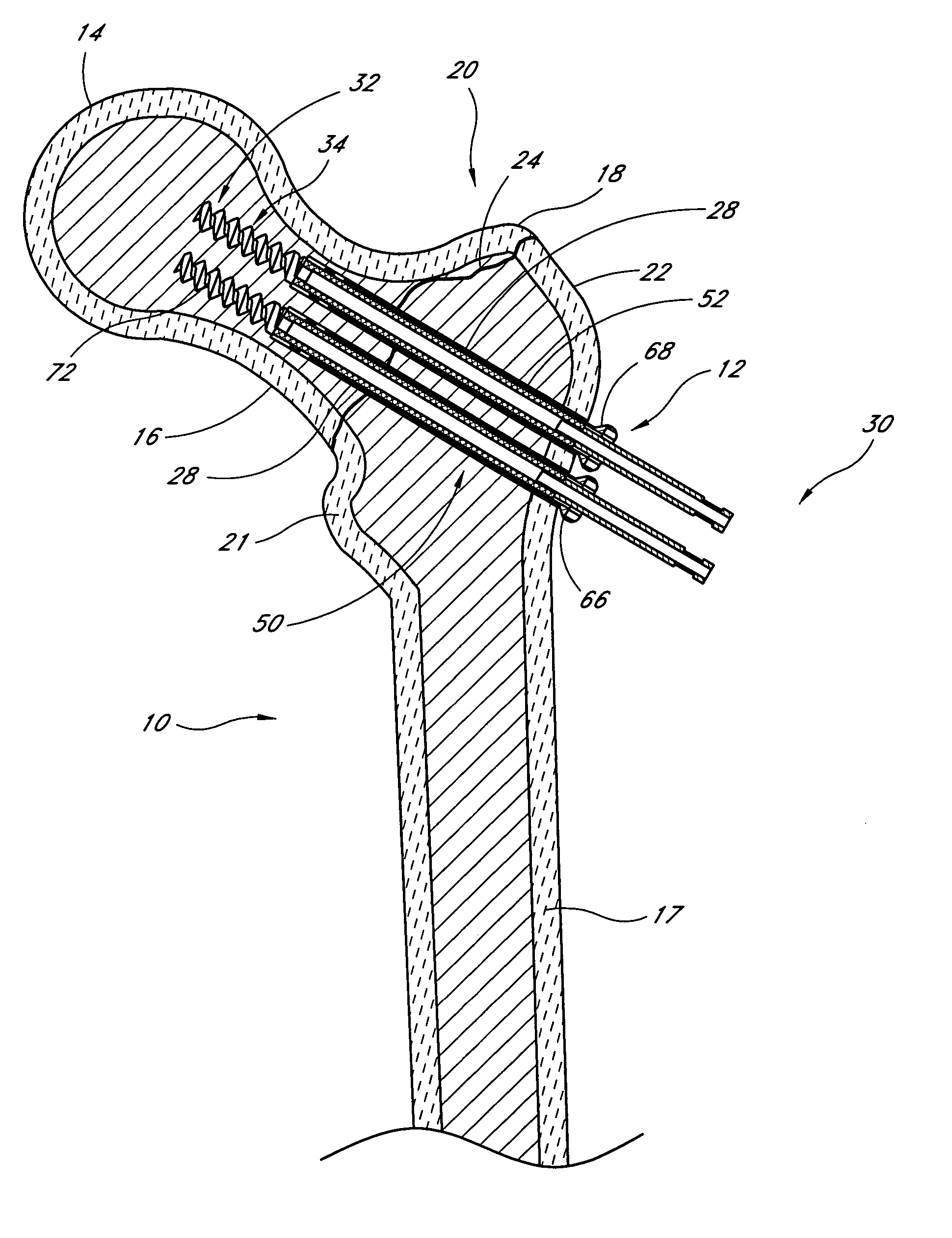
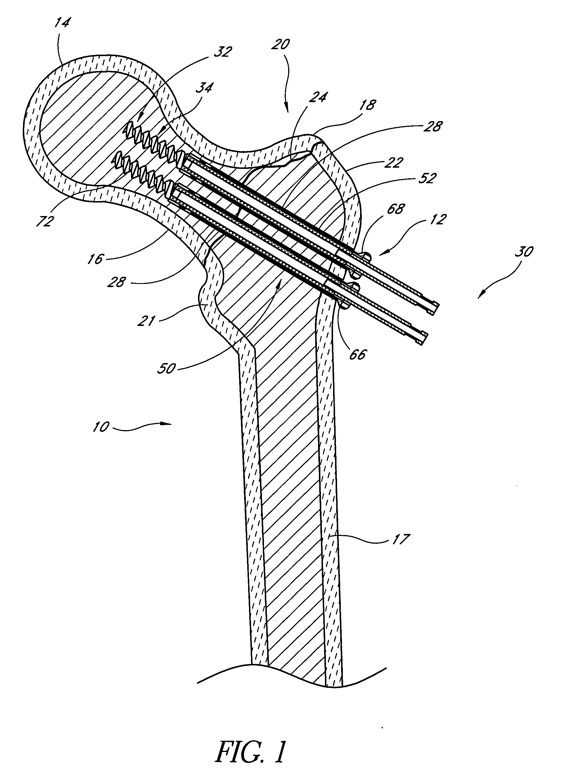
[0041] Although the delivery systems and / or fixation devices of the present invention will be disclosed primarily in the context of delivering bone treatment material (e.g., a medical or orthobiologic agent) to fractures of the proximal femur, the methods and structures disclosed herein are intended for application in any of a wide variety of bones and fractures, as will be apparent to those of skill in the art in view of the disclosure herein. Additionally, the fixation devices and delivery assemblies of the disclosed embodiments can deliver bone treatment agents to one or more locations in a bone. The delivery system of the present invention is applicable in a wide variety of fractures and osteotomies in the hand, such as interphalangeal and metacarpophalangeal arthrodesis, transverse phalangeal and metacarpal fracture fixation, spiral phalangeal and metacarpal fracture fixation, oblique phalangeal and metacarpal fracture fixation, intercondylar phalangeal and metacarpal fracture ...


PUM


Abstract

A fracture fixation device is configured for reducing and compressing fractures in a bone and delivering bone treatment agents. The fixation device includes an elongate body comprising a first portion and a second portion that are detachably coupled to each other. The first portion defines a helical cancellous bone anchor and the second portion defines a distal end. An axially moveable proximal anchor is carried by the proximal end of the fixation device and is rotationally locked to the first portion. The device is rotated into position across the femoral neck and into the femoral head, and the proximal anchor is distally advanced to lock the device into place. The second portion is then detached from the first portion.

Description

RELATED APPLICATIONS [0001] This application claims the priority benefit under 35 U.S.C. § 119(e) of the provisional application 60 / 603,176, filed Aug. 20, 2004, which is hereby incorporated by reference in its entirety.BACKGROUND OF THE INVENTION [0002] 1. Field of the Invention [0003] The present invention relates to bone fixation devices and medical agents. In one application, the present invention relates to bone fixation devices and methods adapted for delivery of a medical agent via the bone fixation devices. [0004] 2. Description of the Related Art [0005] The femur, otherwise known as the thigh bone, generally comprises an elongate shaft extending from the hip to the knee. The proximal end of the shaft includes a head, a neck, a greater trochanter and a lesser trochanter. The head of the femur fits into the acetabular cup of the hip bone to form a ball and socket joint at the hip. The distal end of the femur includes a medial condyle and a lateral condyle. The condyles engage...

Claims


Application Information

Patent Timeline
Patent Type & Authority Applications(United States)
IPC IPC(8): A61F2/30
CPCA61B17/68A61B17/7098A61B17/742A61B17/8888
Inventor CULBERT, BRAD S.WARREN, CHRISTOPHER R.
Owner INTERVENTIONAL SPINE
Why Eureka
Try Eureka