Retaining assembly for rack cabinet

a technology for retaining assemblies and rack cabinets, which is applied in the direction of cabinets, furniture parts, cabinets, etc., can solve the problems of relatively high cost of floating screws b>900/b>

Inactive Publication Date: 2005-08-16
HON HAI PRECISION IND CO LTD
View PDF11 Cites 32 Cited by
  • Summary
  • Abstract
  • Description
  • Claims
  • Application Information

AI Technical Summary

Benefits of technology

[0006]Accordingly, an object of the present invention is to provide a retaining assembly for a rack cabinet which is relatively inexpensive.

Problems solved by technology

However, the float screws 900 are relatively expensive.

Method used


Image

  • Retaining assembly for rack cabinet
  • Retaining assembly for rack cabinet
  • Retaining assembly for rack cabinet

Examples


Embodiment Construction

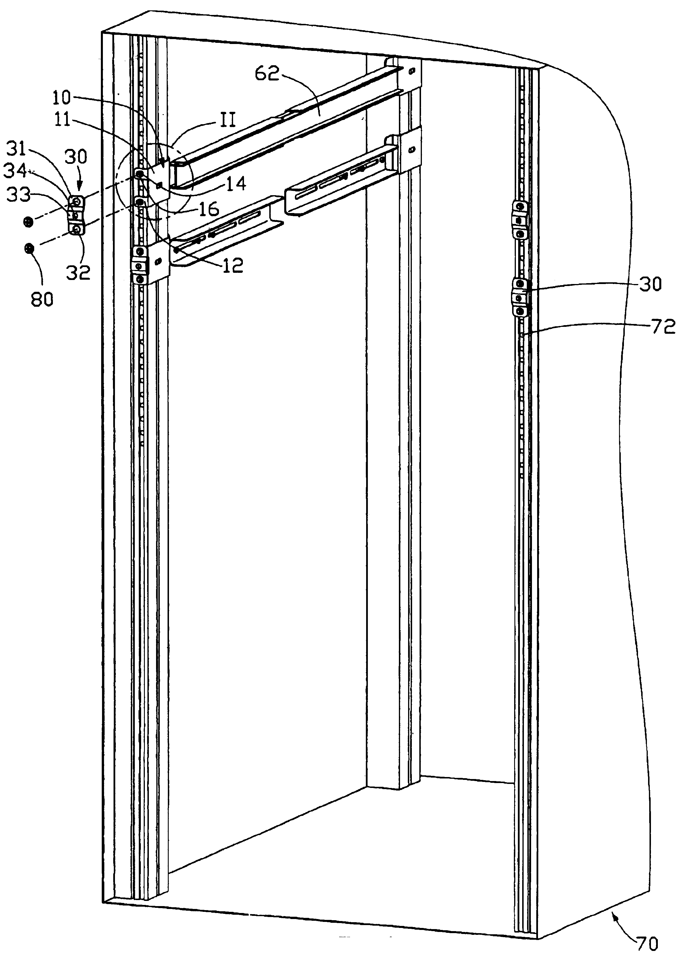
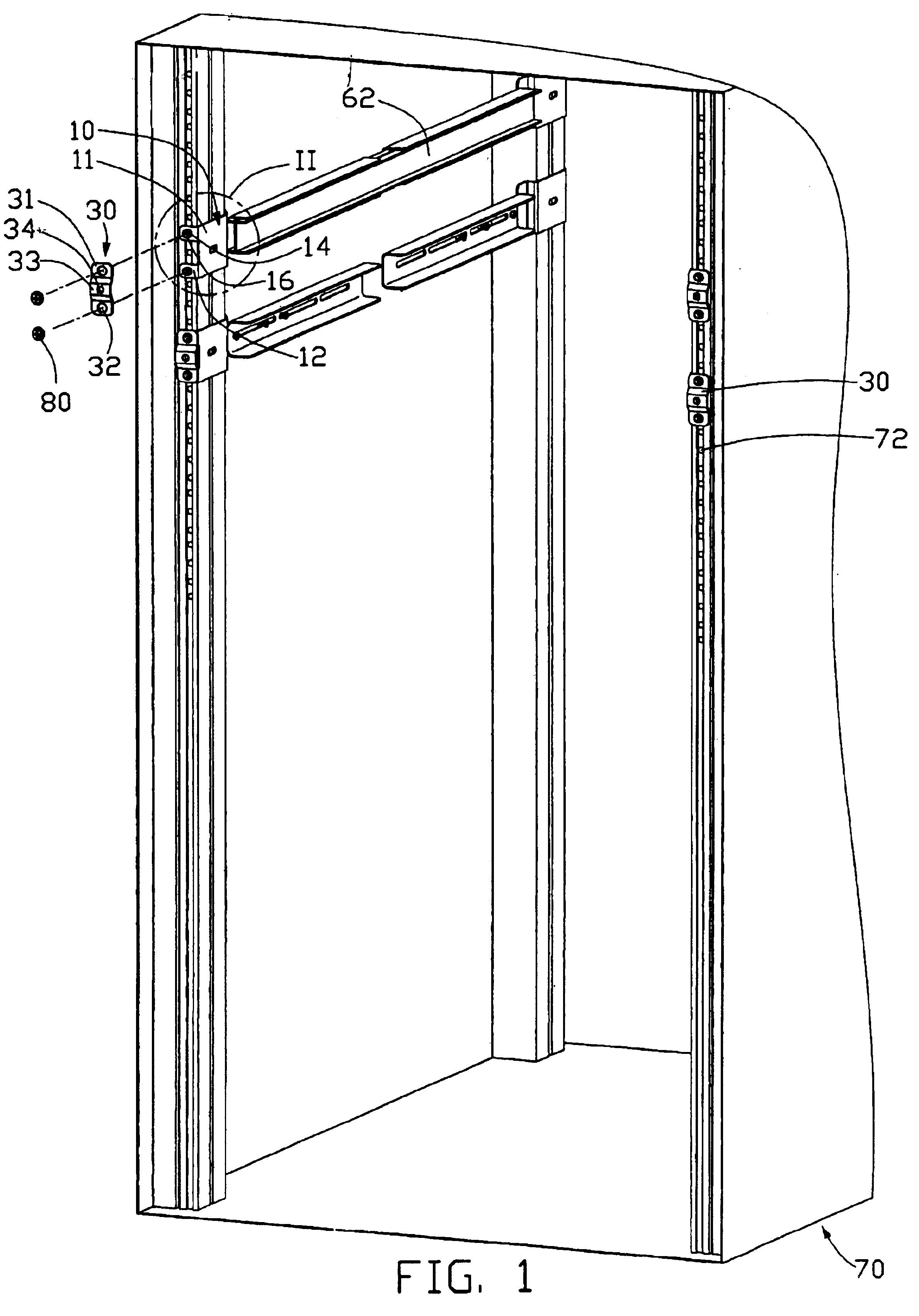
[0018]Referring to FIGS. 1 and 4, a retaining assembly for a rack cabinet in accordance with the present invention comprises a cabinet 70, a first rail assembly, a second rail assembly, a plurality of screws 80, a server 60, a pair of metal plates 30, a pair of fastening plates 50, and a pair of thumbscrews 90.

[0019]Referring to FIGS. 1 and 2, a plurality of threaded holes 72 is defined in front and rear ends of two sidewalls of the cabinet 70.

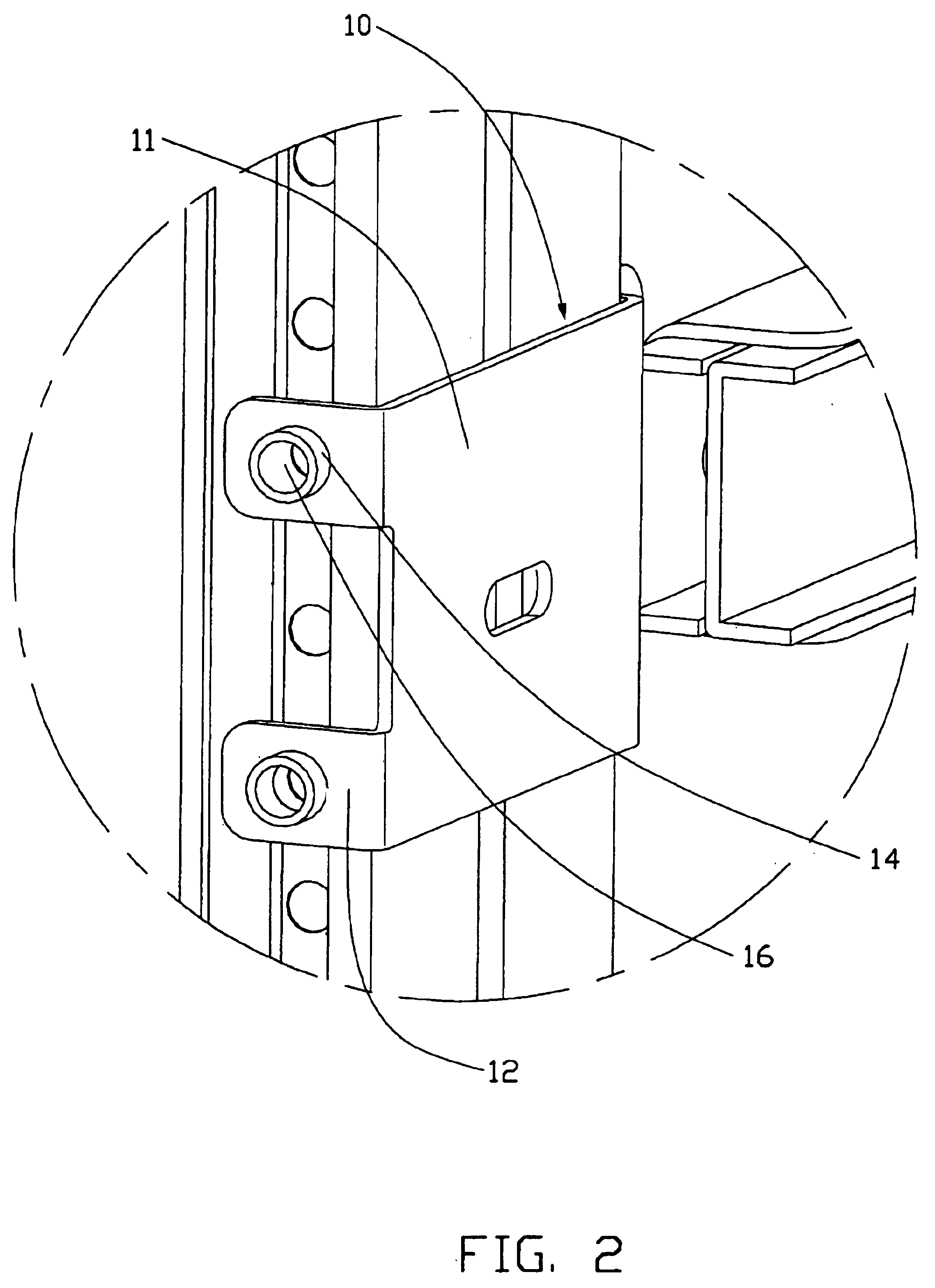
[0020]The first rail assembly comprises a group of rail brackets 10 positioned in the cabinet 70, a pair of outer rails 62, and a plurality of screws 80. Each group of rail brackets 10 comprises two pairs of rail brackets 10, each pair of rail brackets 10 being located in a respective one of opposite sides of the cabinet 70. Each pair of rail brackets 10 comprises two rail brackets 10 located at front and rear portions respectively of a respective side of the cabinet 70. Each rail bracket 10 comprises a main body 11, and two spaced shoulders 1...


PUM


Abstract

A retaining assembly includes a cabinet (70), a first rail assembly located in the cabinet, a pair of metal plates (30) attached on the first rail assembly, a server (60), a second rail assembly attached to two sides of the server, two fastening plates (50) attached to the two sides of the server and two thumbscrews (90). A plurality of threaded holes (72) is defined in two sidewalls of the cabinet. Two first protrusions (14) are provided in the first rail assembly. Each metal plate has two positioning holes (32) and a fixing hole (34). The first protrusions engagably extend through the positioning holes respectively. Each fastening plate has an inserting hole (56) corresponding to the fixing hole of the metal plate. The thumbscrews are inserted through corresponding inserting holes of the metal plates to engage in corresponding fixing holes of the metal plates.

Description

BACKGROUND OF THE INVENTION[0001]1. Field of the Invention[0002]The present invention relates to a retaining assembly for a rack cabinet, and particularly to a retaining assembly employing low-cost conventional screws.[0003]2. Prior Art[0004]Referring to FIGS. 8 and 9, a conventional server 600 is mounted to a cabinet 700 by four rail brackets 100, two outer rails 620 positioned in the brackets 100, two inner rails (not shown) fixed to opposite sides of the server 600 respectively, two fixing plates 500 attached to the opposite sides of the server 600 respectively, a plurality of screws 800 and two float screws 900. Each rail bracket 100 comprises two shoulders 120, and a mounting portion 180. Each rail bracket 100 is fastened to the cabinet 700 by inserting the screws 800 through the shoulders 120 to engage in corresponding threaded holes (not labeled) in the cabinet 700. A pair of float screws 900 is attached to the fixing plates 500. The server 600 is inserted into the cabinet 70...

Claims


Application Information

Patent Timeline
Patent Type & Authority Patents(United States)
IPC IPC(8): H05K7/14
CPCH05K7/1421H05K7/1489
Inventor LIU, ALVINFAN, CHEN-LUCHEN, LI-PING
Owner HON HAI PRECISION IND CO LTD
Why Eureka
Try Eureka