Tile positioning device for a tile cutting machine

a positioning device and cutting machine technology, applied in the direction of working accessories, manufacturing tools, working apparatuses with stone-like materials, etc., can solve problems such as unfavorable positioning

Inactive Publication Date: 2005-08-23
MOTOMAX ELECTRIC
View PDF7 Cites 31 Cited by
  • Summary
  • Abstract
  • Description
  • Claims
  • Application Information

AI Technical Summary

Problems solved by technology

Nevertheless, the plate of the positioning device 17 is not engaged with the gauge 16 so that it is not well positioned when moving along the side of the gauge 16.

Method used


Image

  • Tile positioning device for a tile cutting machine
  • Tile positioning device for a tile cutting machine
  • Tile positioning device for a tile cutting machine

Examples


Embodiment Construction

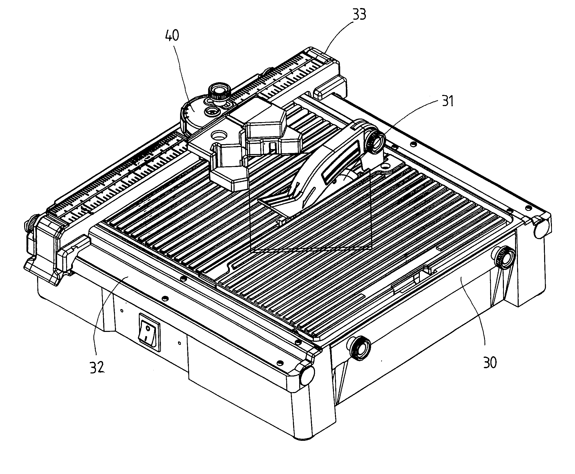
[0016]Referring to FIGS. 3 to 5, the tile cutting machine of the present invention comprises a base 30 having two rails 32 on two sides thereof and a blade 31 rotatably extends through a slot defined through a top surface of the base 30. A fence is pivotably mounted to the blade 31. A gauge 33 is slidably mounted between two rails 32 and a positioning device 40 is slidably engaged with an inside side of the gauge 33.

[0017]The positioning device 40 comprises a first piece 41 which has an engaging wall 411 extending from an underside thereof and a first tube 413, a second tube 414 and a third tube 415 respectively extend from a top of the first piece 41. The second tube 414 located at a center of the first piece 41. A spring 4141 and a bead 4142 are received in the second tube 414. The first piece 41 is overlapped on the gauge 33 and the gauge 33 is engaged with the recess 412 defined by the engaging wall 411 and the horizontal portion of the first piece 41, such that an inside of the...


PUM

PropertyMeasurementUnit
anglesaaaaaaaaaa
sizeaaaaaaaaaa
distanceaaaaaaaaaa

Abstract

A tile positioning device of a tile cutting machine includes a first piece slidably engaged with the gauge and a second piece is pivotably connected to the first piece. The second piece includes two protrusions and a right angle is defined between two surfaces of the two protrusions for clamping two sides of a tile and the tile can be rotated relative to the blade of the cutting machine by rotating the second piece. A third piece is optionally and pivotably connected to one of the two protrusions for adjusting the positioning of the tile.

Description

FIELD OF THE INVENTION[0001]The present invention relates to a tile positioning device of a tile cutting machine wherein the positioning device allows the tile to be positioned at desired angles.BACKGROUND OF THE INVENTION[0002]A conventional tile cutting machine 10 is shown in FIGS. 1 and 2 and generally includes a base 11 with a chamber 12 defined therein in which a motor (not shown) and a blade 14 are installed. A cover 13 is used to close the chamber and is in flush with the top surface of the tile cutting machine 10. The blade 14 extends from a slot defined through the top surface of the base 11 so as to cut the tile 20 positioned on the top surface of the machine 10. A gauge 16 is mounted about the top surface of the machine 10 and two ends of the gauge 16 are slidably engaged with two rails 15 on two sides of the base 10. A positioning device 17 includes a plate which includes a straight side 171 and a recess 172, wherein the straight side 171 is used to slidably contact on a...

Claims


Application Information

Patent Timeline
Patent Type & Authority Patents(United States)
IPC IPC(8): B28D7/00B28D7/04B27B25/00B27B25/10B27B27/02B27B27/00
CPCB27B25/10B27B27/02B28D7/043
Inventor CHENG, CHIN MINGLIN, CHOU JENQ
Owner MOTOMAX ELECTRIC
Why Eureka
Try Eureka