Damped drawer slide mechanism

a technology of sliding mechanism and drawer slide, which is applied in the direction of elastic bearings, rigid support of bearings, furniture parts, etc., can solve the problems of unfavorable sudden movement, rapid closing, and further dampening

Active Publication Date: 2005-08-23
ILLINOIS TOOL WORKS INC
View PDF3 Cites 16 Cited by
  • Summary
  • Abstract
  • Description
  • Claims
  • Application Information

AI Technical Summary

Benefits of technology

[0009]In another aspect thereof, the present invention provides a damper mechanism with a base and a gear damper including a housing secured to the base. A rotor rotatably disposed in the housing extends outwardly therefrom. A gear is drivingly connected to the rotor. A body rotatably disposed on the base has gear teeth drivingly engaging the gear on the rotor. The body includes an arm projecting therefrom and adapted to engage a structure, the relative movement of which is to be damped.
[0010]In still another aspect thereof, the present invention provides a

Problems solved by technology

However, an assist having sufficient strength to close automatically a heavily loaded drawer or the like can cause undesirably abrupt movements and rapid closing, with significant impact upon reaching the fully closed position, especially when the d

Method used


Image

  • Damped drawer slide mechanism
  • Damped drawer slide mechanism
  • Damped drawer slide mechanism

Examples


Embodiment Construction

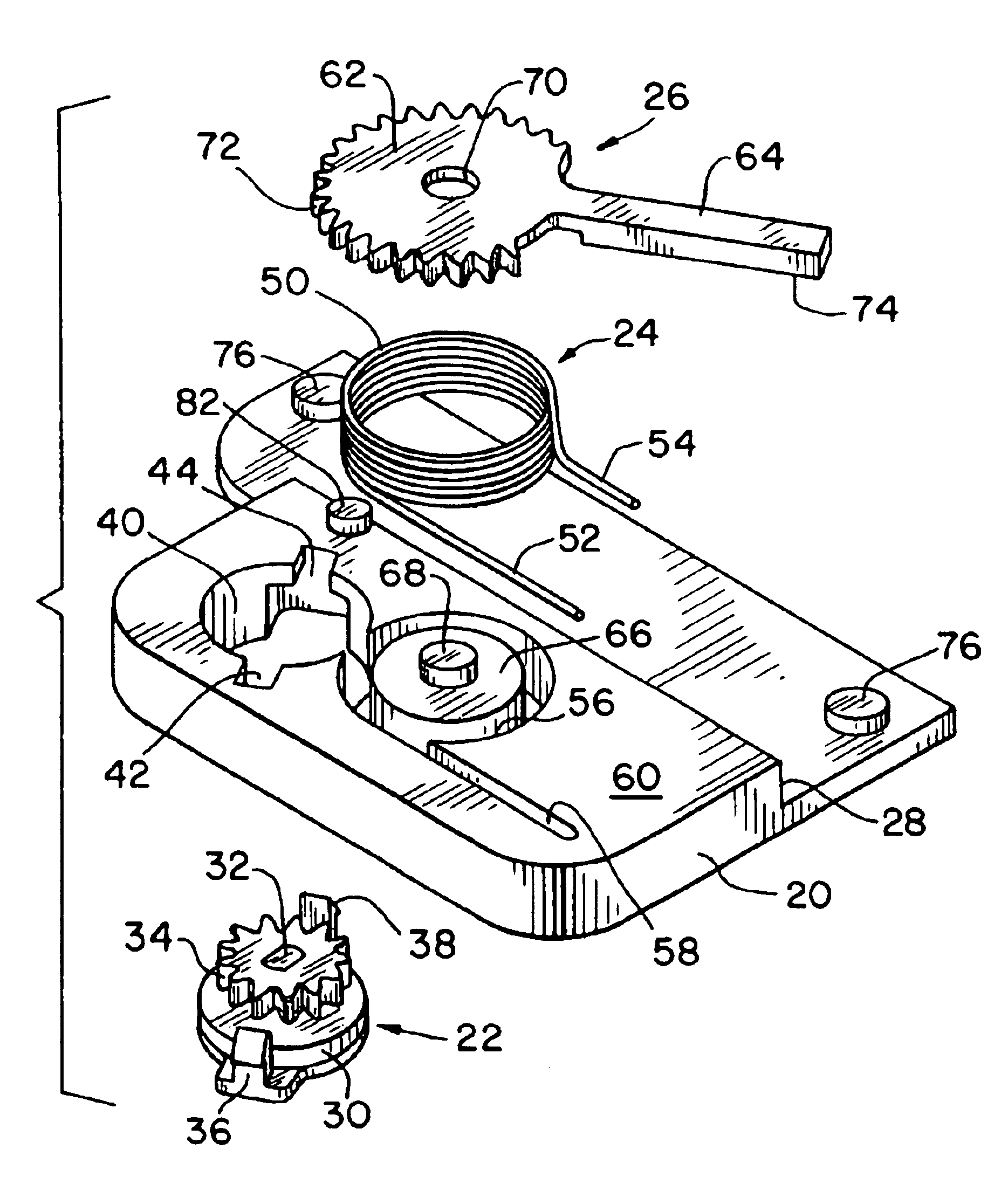
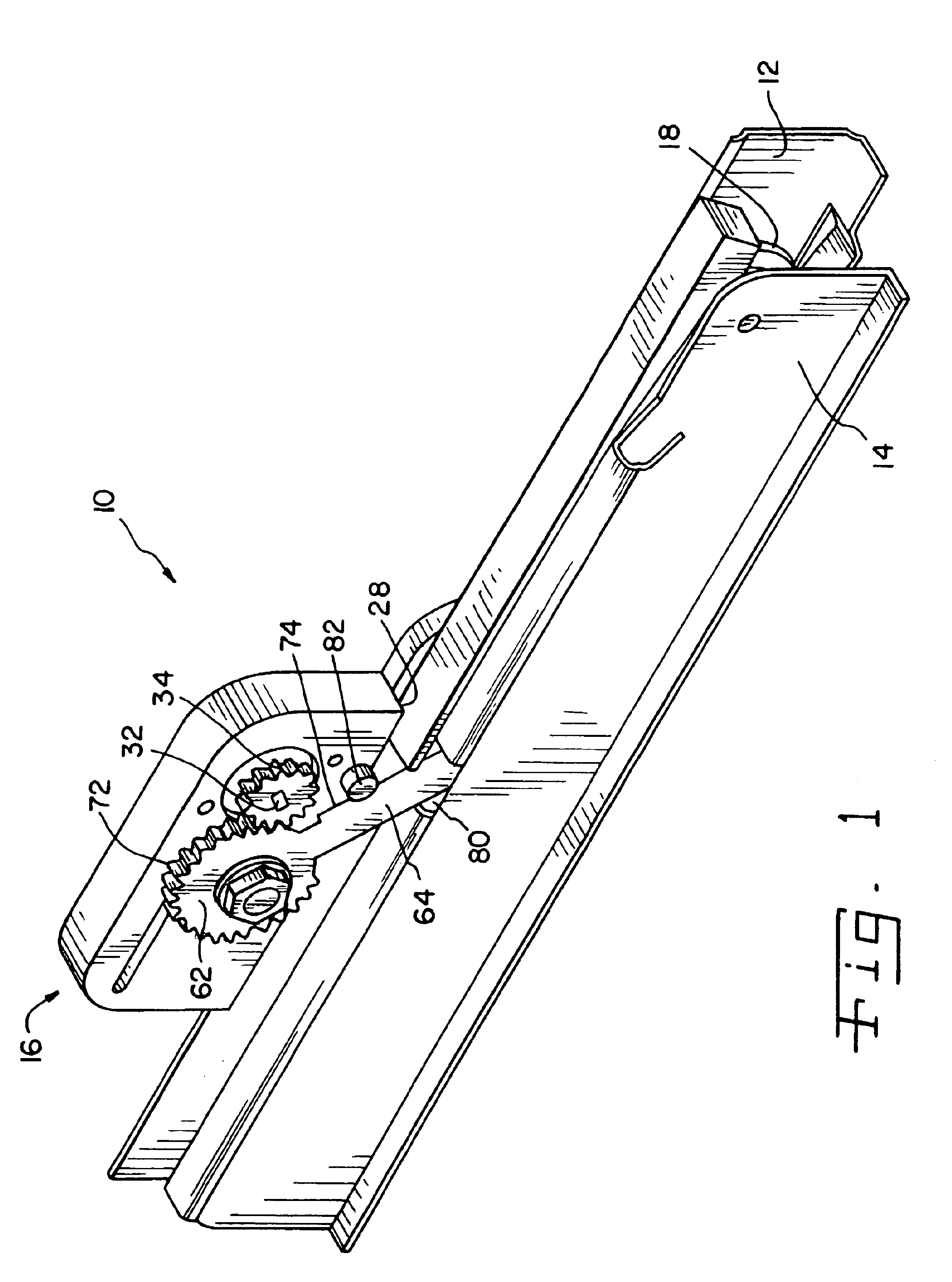
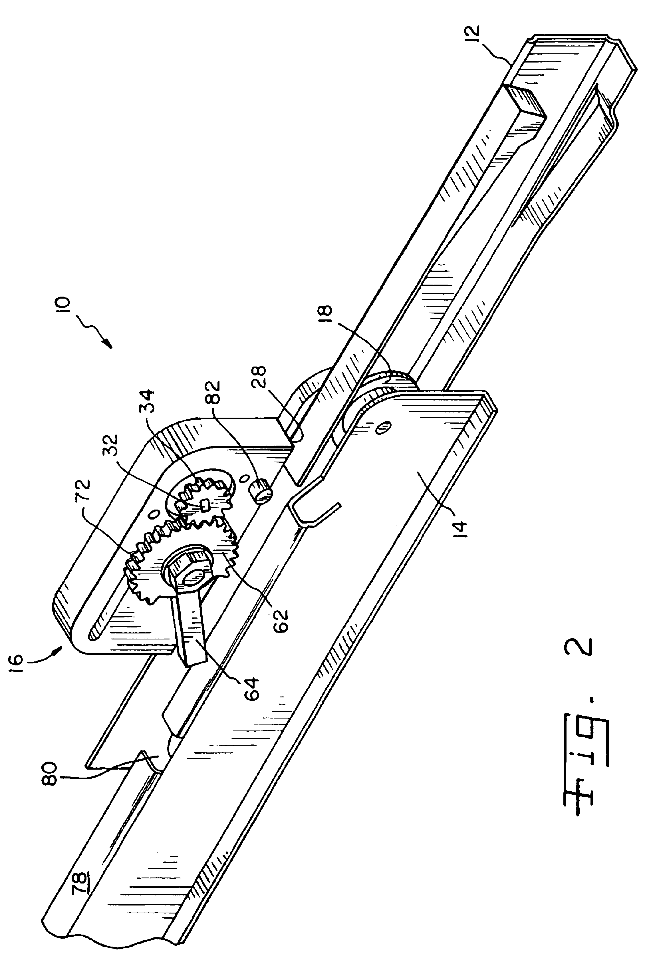
[0017]Referring now more specifically to the drawings and to FIG. 1 in particular, a damped draw slide mechanism 10 in accordance with the present invention is shown. Drawer slide mechanism 10 includes a stationary rail 12 and a movable rail 14. A damper mechanism 16 is operatively associated with rails 12 and 14 to provide a measure of control on the relative sliding movement between rails 12 and 14.

[0018]In the exemplary embodiment shown, damped drawer slide mechanism 10 is particularly suitable for use on a drawer such as in a cabinet or the like, and rails 12 and 14 are designed for attachment to the drawer frame (not shown) and drawer (not shown), respectively. It should be understood that the size and shape of rails of 12 and 14 may vary, depending on the size and capacity of the drawer, shelf, cabinet or the like to which each is attached. The concepts of the present invention work advantageous with a variety of rail and support configurations.

[0019]Those skilled in the art w...


PUM


Abstract

A slide mechanism includes first and second rails connected for relative sliding movement with respect to each other. A damper mechanism is secured to one of the rails and can be connected to and disconnected from the other of the rails to provide a damping effect for relative movement of the rails during at least a part of the movement thereof.

Description

CROSS-REFERENCE TO RELATED APPLICATIONS[0001]The present regular application claims the benefits of U.S. Provisional Application Ser. No. 60 / 459,552 filed on Apr. 1, 2003.FIELD OF THE INVENTION[0002]The present invention relates to sliding-type closure mechanisms such as those used on kitchen drawers, sliding racks, desk drawers and other cabinets and the like. More particularly, the invention relates to self-closing sliding closure mechanisms having dampers for controlling the rate of movement in at least one direction.BACKGROUND OF THE INVENTION[0003]For closure mechanisms on racks and drawers in kitchen cabinets, storage units, furniture and the like often it is convenient and helpful to utilize spring assists for moving the mechanism in one direction, typically in the closing direction. With spring assists, the mechanism can be made self-closing, requiring only an initial start to unseat it from a secured, opened position. The mechanism can reduce the effort required for closing...

Claims


Application Information

Patent Timeline
IPC IPC(8): A47B88/04
CPCA47B88/047A47B88/467
Inventor DOORNBOS, DAVID A.BIVENS, STEVEN L.
Owner ILLINOIS TOOL WORKS INC
Why Eureka
Try Eureka