Motor driver

a motor and driver technology, applied in the direction of motor/generator/converter stopper, electronic commutator, dynamo-electric converter control, etc., can solve the problems of noise, brushless motor b>1/b> rotating with torque fluctuations and distortion of current level of driving output current output from driving control circui

Inactive Publication Date: 2005-08-23
ROHM CO LTD
View PDF5 Cites 12 Cited by
  • Summary
  • Abstract
  • Description
  • Claims
  • Application Information

AI Technical Summary

Benefits of technology

[0015]An object of the present invention is to provide a motor driver that normalizes the amplitude of the position signals that represent the rotation position of the rotor of a brushless motor and that achieves PWM drive control by the use of those normalized position signals.

Problems solved by technology

However, when the amplitude of the Hall signals from the Hall elements 2a to 2c is so large that the amplitude of the pseudo-sinusoidal signals obtained by multiplying the Hall signals by the torque error signal is larger than the level corresponding to about twice the PWM conversion pulse width, distortion occurs in the current level of the driving output currents outputted from the driving control circuit 11.
This makes it impossible to smoothly drive the three-phase coil (not illustrated) of the brushless motor 1 with the pseudo-sinusoidal signals, with the result that the brushless motor 1 rotates with torque fluctuations and with noise.
This causes the brushless motor 1 to rotate with torque fluctuations and with noise.
On the other hand, when the amplitude of the position signals becomes too small depending on the ambient temperature, the maximum rotation rate becomes lower than is set, resulting in performance lower than is expected.

Method used


Image

  • Motor driver
  • Motor driver
  • Motor driver

Examples


first embodiment

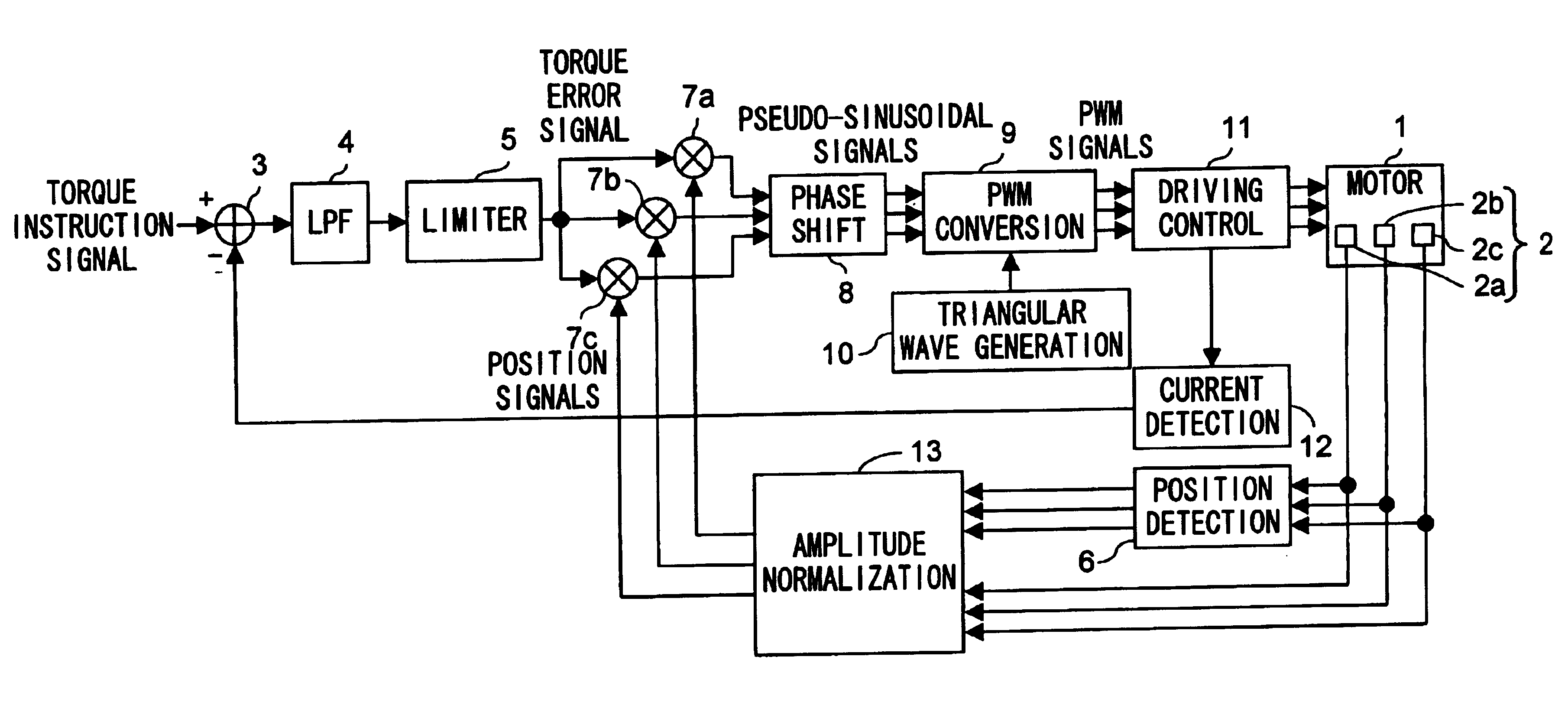
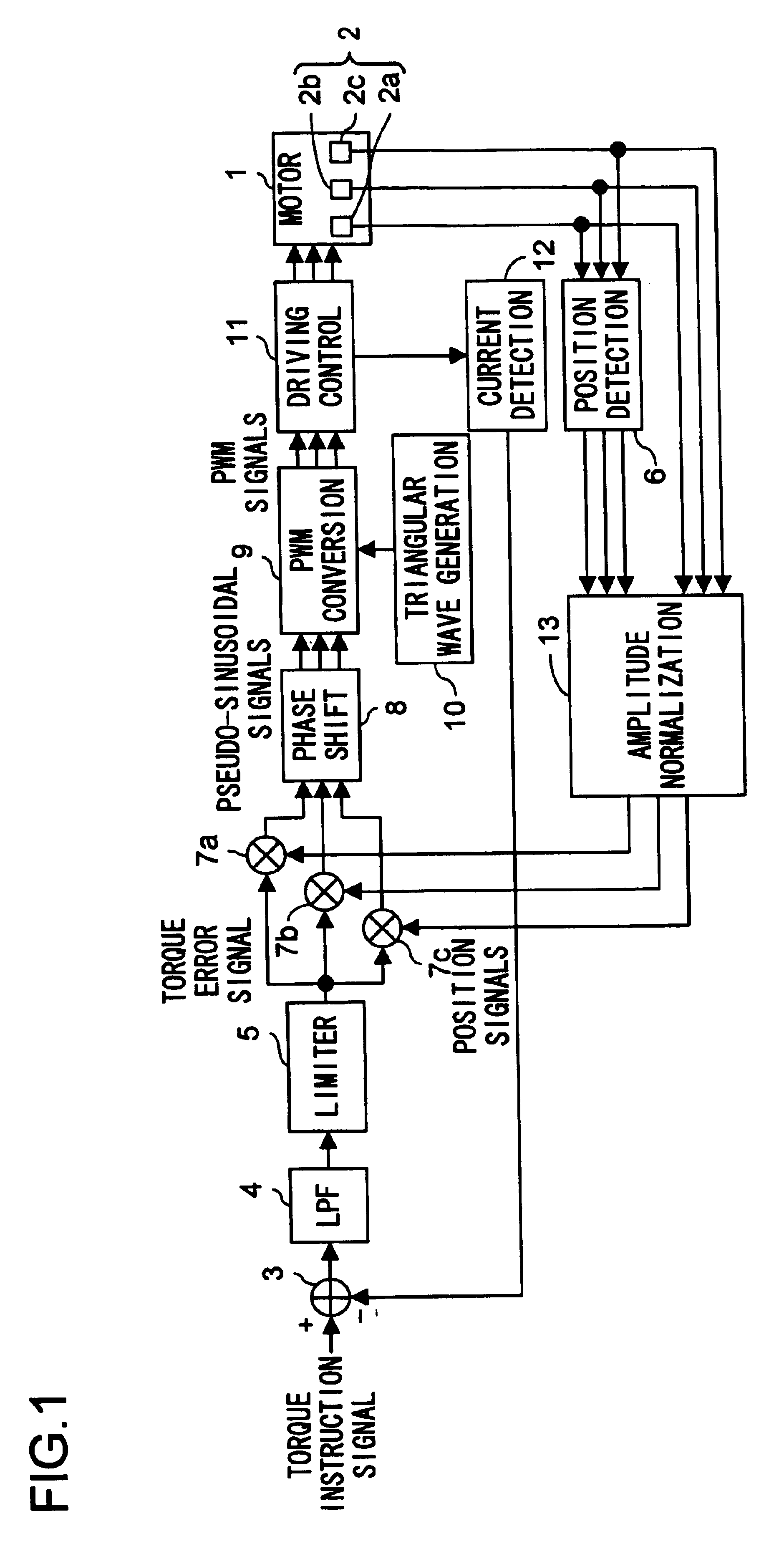
[0026]First, a first embodiment of the present invention will be described with reference to the drawings. FIG. 1 is a block diagram showing the configuration of the three-phase motor driver of the first embodiment. In the motor driver shown in FIG. 1, such blocks as are found also in FIG. 6 are identified with the same reference numerals, and their detailed explanations will not be repeated.

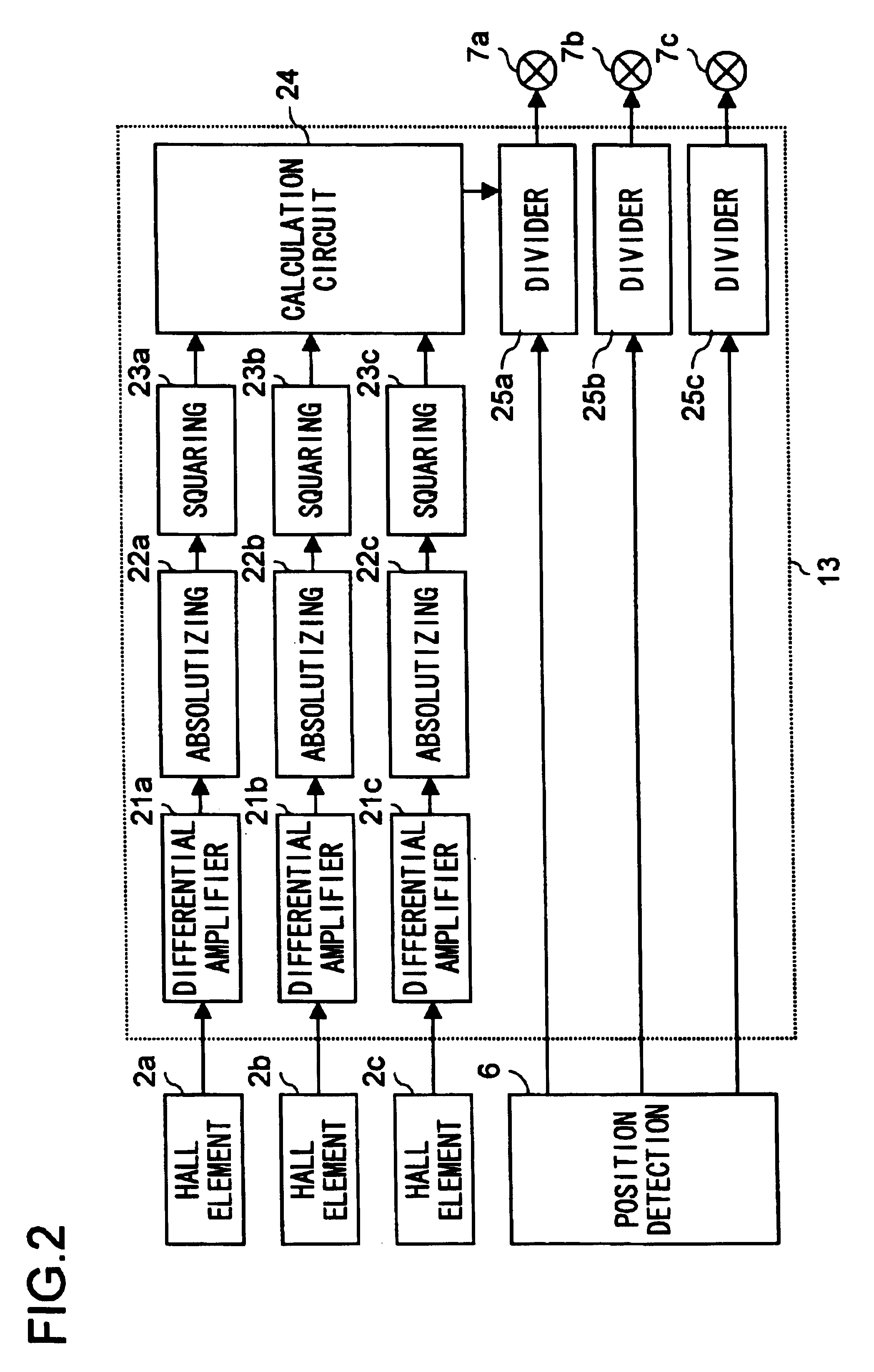
[0027]The motor driver shown in FIG. 1, as compared with the configuration shown in FIG. 6, additionally includes an amplitude normalization circuit 13 that normalizes the amplitude of the position signals from the position detection circuit 6. As shown in FIG. 2, this amplitude normalization circuit 13 includes: differential amplifier circuits 21a to 21c that differentially amplify the Hall signals, composed of a pair of a positive and a negative signal for each phase, from the Hall elements 2a to 2c respectively; absolutizing circuits 22a to 22c that absolutize the outputs of the differential ...

second embodiment

[0036]Next, a second embodiment of the present invention will be described with reference to the drawings. FIG. 4 is a block diagram showing the configuration of the motor driver of the second embodiment. In the motor driver shown in FIG. 4 and the amplitude normalization circuit shown in FIG. 5, such blocks as are found also in FIGS. 1 and 2 are identified with the same reference numerals, and their detailed explanations will not be repeated.

[0037]The motor driver shown in FIG. 4 includes, instead of the amplitude normalization circuit 13 shown in FIG. 1, an amplitude normalization circuit 14 that feeds the Hall signals from the Hall elements 2a to 2c to the position detection circuit 6 after normalizing the amplitude of those signals. As shown in FIG. 5, this amplitude normalization circuit 14 includes: differential amplifier circuits 21a to 21c; absolutizing circuits 22a to 22c; squaring circuits 23a to 23c; a calculation circuit 24x that multiplies by (⅙)0.5×2 the value obtained...


PUM

PropertyMeasurementUnit
n-phaseaaaaaaaaaa
current levelaaaaaaaaaa
currentaaaaaaaaaa

Abstract

An amplitude normalization circuit 13 finds the amplitude of position signals outputted from a position detection circuit 6 on the basis of Hall signals from Hall elements 2a to 2c. The position signals from the position detection circuit 6 are then divided by the thus found amplitude and are thereby normalized. Multiplier circuits 7a to 7c then multiply by a torque error signal limited by a limiter 5 the position signals normalized by the amplitude normalization circuit 13 to generate pseudo-sinusoidal signals.

Description

[0001]This application is based on Japanese Patent Application No. 2003-028331 filed on Feb. 5, 2003, the contents of which are hereby incorporated by reference.BACKGROUND OF THE INVENTION[0002]1. Field of the Invention[0003]The present invention relates to a motor driver for a brushless motor provided with Hall elements for detecting the rotation position of the rotor, such as a spindle motor used in a CD (compact disk) or DVD (digital versatile disk) drive.[0004]2. Description of the Prior Art[0005]Some conventional brushless motors are of the type that recognizes the rotation position of the rotor by the use of Hall elements and that performs feedback control on the basis of the Hall signals from those Hall elements. As an example of such brushless motors that perform feedback control on the basis of Hall signals, there has been proposed a motor speed controller that recognizes the rotation angle of a motor on the basis of Hall signals and eliminates motor torque ripple component...

Claims


Application Information

Patent Timeline
Patent Type & Authority Patents(United States)
IPC IPC(8): H02P6/14H02P6/16H02P6/06G11B19/28H02P6/08H02P6/10H02P6/28
CPCH02P6/16G11B19/28
Inventor YAMAMOTO, SEIICHI
Owner ROHM CO LTD
Why Eureka
Try Eureka