Surgical operation instrument

a surgical operation and instrument technology, applied in the field can solve the problems of inability to execute suture and ligature with high efficiency, difficult operation of surgical operation instruments, and inability to ensure the engagement of finger segments

Inactive Publication Date: 2005-08-30
OLYMPUS CORP
View PDF8 Cites 278 Cited by
  • Summary
  • Abstract
  • Description
  • Claims
  • Application Information

AI Technical Summary

Problems solved by technology

The surgical operation instrument disclosed in U.S. Pat. No. 5,908,436 has problems in that the distance to the finger engagement portion is inevitably changed whenever the grip is held and the wrist is moved.
Since the degree of finger engagement varies accordingly, the surgical operation instrument is not very easy to operate.
Hence, suture and ligature cannot be executed with high efficiency.

Method used


Image

  • Surgical operation instrument
  • Surgical operation instrument
  • Surgical operation instrument

Examples


Embodiment Construction

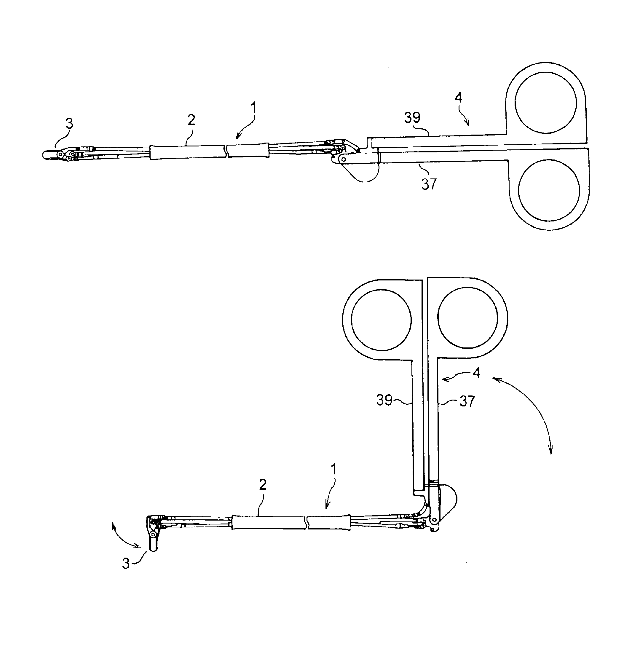
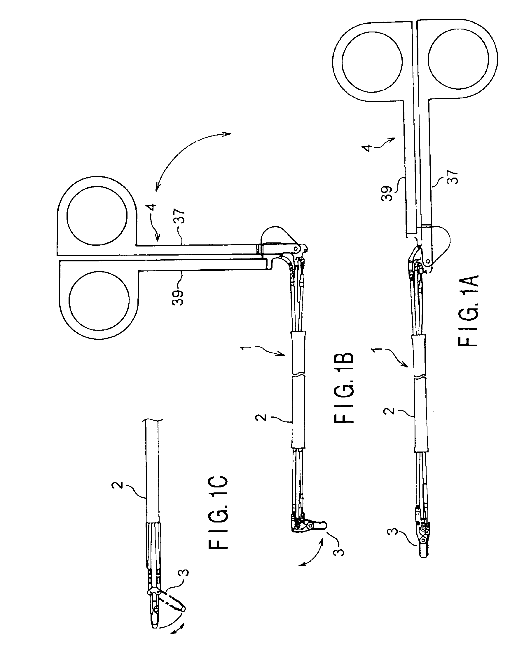
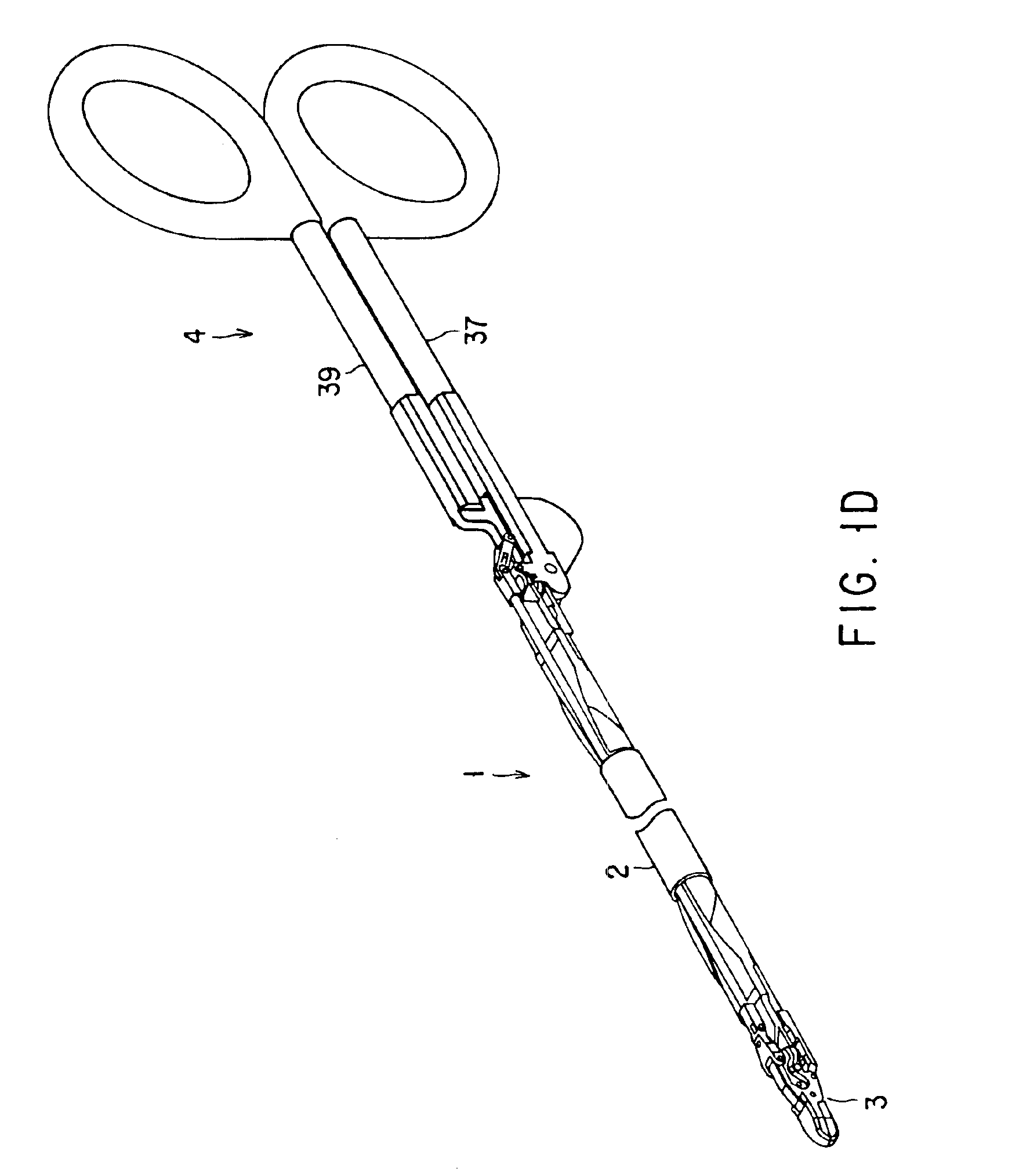
[0038]FIG. 1A to FIG. 4 show the first embodiment. FIGS. 1A-1G show the entire structure of a surgical operation instrument. Of these Figures, FIG. 1A is a side view showing the linear state, FIG. 1B is a side view showing how a treatment section and an operation section are rotated, FIG. 1C is a view showing the lower portion of the distal end of the insertion section, FIG. 1D is a perspective view showing the state in which the operation section and the treatment section are horizontal relative to the insertion section of the embodiment, FIG. 1E is a perspective view showing the state where the operation section is turned vertically upward and the treatment section is turned vertically downward relative to the insertion section, FIG. 1F is a perspective view showing the state where the operation section is turned leftward and the treatment section is turned rightward relative to the insertion section, and FIG. 1G is a perspective view showing the state where the insertion section ...


PUM


Abstract

The present invention is provided with a treatment section provided at the distal end of an insertion section insertable into a body cavity, and being openable / closable and rotatable from side to side and up and down, an operation section provided at the proximal end of the insertion section and being openable / closable and rotatable from side to side and upward or downward, and first to third driving rods which connect the treatment section and the operation section together and which can be advanced or retracted. The present invention is characterized in that the opening / closing operation of the first and second handles causes the advancing / retracting movement of the driving rod, thereby opening or closing the jaws of the treatment section, and in that the rotation of the operation section causes the advancing / retracting movement of the driving rod, thereby rotating the treatment section relative to the axis of the insertion section.

Description

CROSS REFERENCE TO RELATED APPLICATIONS[0001]This is a Continuation Application of PCT Application No. PCT / JP01 / 03400, filed Apr. 20, 2001, which was not published under PCT Article 21(2) in English.[0002]This application is based upon and claims the benefit of priority from the prior Japanese Patent Application No. 2000-128265, filed Apr. 27, 2000, the entire contents of which are incorporated herein by reference.BACKGROUND OF THE INVENTION[0003]1. Field of the Invention[0004]The present invention relates to a surgical operation instrument whose operation section, located at the proximal end of an insertion section, is gripped by the operator and whose treatment section, located at the distal end of the insertion section, is rotated and opened / closed, for surgical operation.[0005]2. Description of the Related Art[0006]As shown, for example, in U.S. Pat. No. 5,908,436, a surgical operation instrument comprises a shaft, an openable / closable treatment section located at the distal end...

Claims


Application Information

Patent Timeline
Patent Type & Authority Patents(United States)
IPC IPC(8): A61B17/28A61B17/04A61B17/06A61B17/00A61B17/12
CPCA61B17/0469A61B17/062A61B17/29A61B2017/291A61B2017/2927
Inventor SASAKI, KATSUMI
Owner OLYMPUS CORP
Why Eureka
Try Eureka