System for confocal imaging within dermal tissue

a confocal imaging and dermal tissue technology, applied in the field of confocal imaging systems, can solve the problems of affecting the observation of dermal structures of interest by physicians, affecting the relative field of view of the tissue area, and limiting the optical field of view of the patient's skin tissue, so as to reduce the relative motion of the tissue, the effect of minimizing the instability of the confocal imag

Inactive Publication Date: 2005-08-30
CALIBER IMAGING & DIAGNOSTICS
View PDF29 Cites 46 Cited by
  • Summary
  • Abstract
  • Description
  • Claims
  • Application Information

AI Technical Summary

Benefits of technology

[0004]Accordingly, it is the principal object of the present invention to provide an improved system for confocal imaging within dermal and subdermal tissue of a patient which minimizes instability in confocal images by reducing the relative motion of the tissue with respect to the confocal imaging optics of the system.
[0005]It is another object of the present invention to provide an improved system for confocal imaging of tissue having a mechanical structure, such as a platen, brace, or attachment which both supports the confocal imaging optics of the system and applies stress to a limited surface area of the tissue to minimize skin motion during confocal imaging.

Problems solved by technology

Such optics have a limited field of view of the patient's skin tissue, which for example may cover a tissue area less than one millimeter wide.
One problem with these systems is that motion of the patient during confocal imaging can cause the tissue area being imaged to move relative to the system's confocal optics, shifting the field of view of the tissue area with respect to the optics.
Consequently, confocal images from such systems may appear unstable to the viewing physician, making it difficult for the physician to observe dermal structures of interest.

Method used


Image

  • System for confocal imaging within dermal tissue
  • System for confocal imaging within dermal tissue
  • System for confocal imaging within dermal tissue

Examples


second embodiment

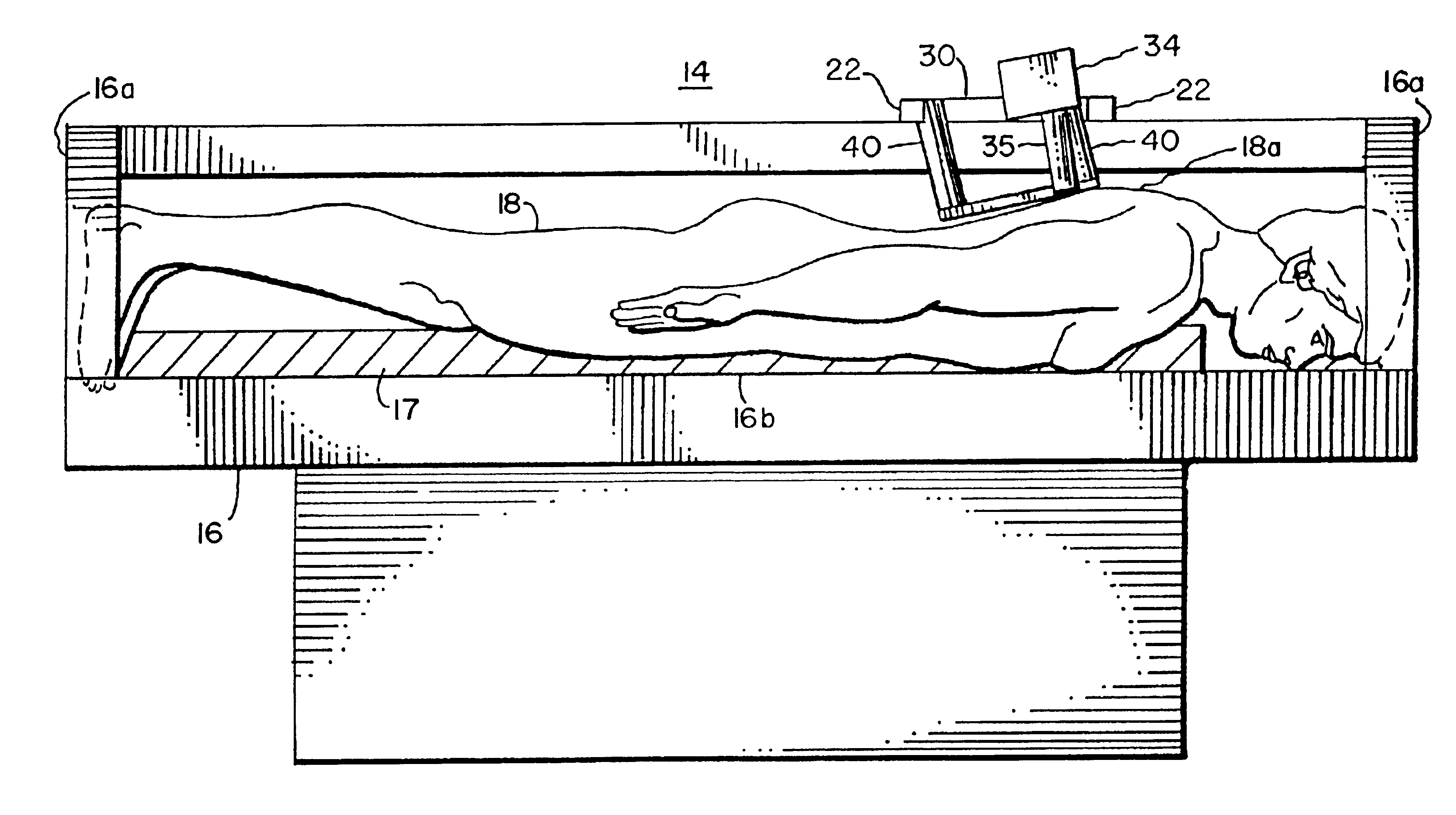
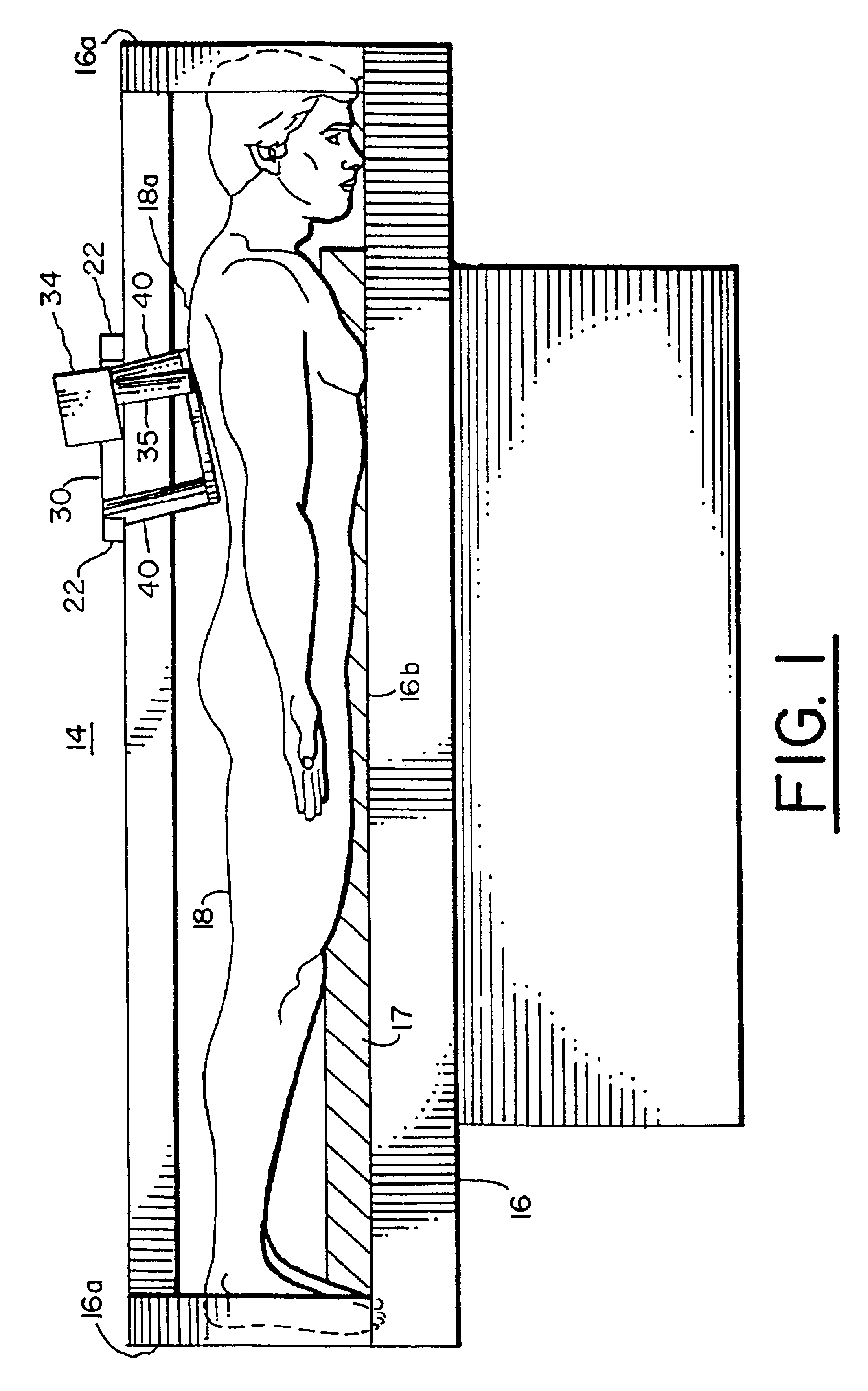
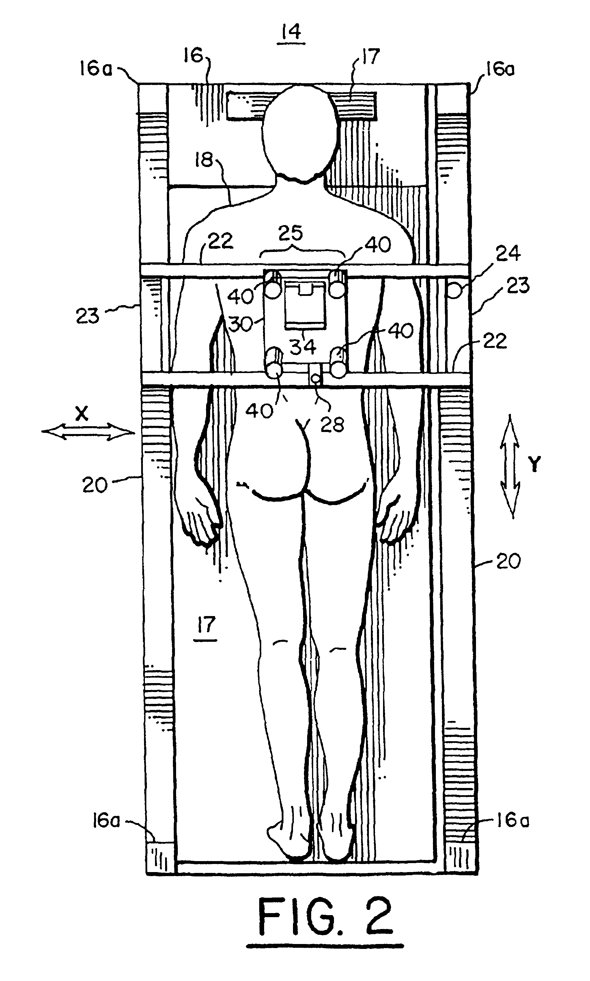
[0029]the present invention is shown in FIGS. 5-8 having a system 58. System 58 includes a brace structure 50 having a rigid lower lamination 52 which is held stationary to the skin tissue 18a of patient 18 by straps 54. Lower lamination 52 is shaped to approximate the curvature of a gross anatomical body part of the patient, such as part of the leg, torso, or arm, as shown in FIG. 5. A bottom 52a of lower lamination 52 has an opening 53, as shown in FIGS. 7 and 8. Bottom 52a defines a well 59 therein between ends 57a and sides 57b of lower lamination 52. Ends 57a and sides 57b define a rigid frame 57. Further, ends 57a and sides 57b have blind slots 55 within which an upper lamination 56 is captured. FIG. 8 shows frame 57 of lower lamination 52 in which upper lamination 56 has been removed for purposes of illustration.

[0030]Upper lamination 56 is a curved rigid sheet parallel with lower lamination 52, and has a confocal viewing window 58 (FIG. 7) substantially smaller than opening ...

third embodiment

[0033]the present invention is shown in FIGS. 9-11. This embodiment is provided by a tissue stabilization system 68 which includes an attachment 69. The tissue is shown at 84 in FIGS. 10-11 as a layer of skin. Attachment 69 includes a flexible diaphragm member 70, a central circular window or plate member 72, and a semi-rigid ring 74. Diaphragm 70 is composed of deformable rubber selected to be less compliant than tissue 84. Diaphragm 70 radially extends from window 72 outward to semi-rigid ring 74. Ring 74 may be composed of hard rubber, while window 72 may be composed of a material having an optical index approximately matching tissue 84. Diaphragm 70 has between ring 74 and window 72 an annular protruding section 75 (protruding in the direction of the arrow of FIG. 10). Section 75 defines outer and inner annular cavities 76 and 78, respectively. Also, attachment 69 has a pair of vacuum lines 80 which each connects different ones of annular cavities 76 and 78 to a pneumatic pump w...


PUM


Abstract

An improved system for confocal imaging within dermal tissue of a patient is provided which minimizes instability in confocal images by reducing the relative motion of the tissue with respect to the confocal imaging optics of the system. The system includes a mechanism for maintaining an area of skin tissue under stress by application of force at the edges of the area, and an imaging head coupled to this mechanism for imaging the stressed skin. The mechanism includes a mechanical structure, such as a platen, brace, or attachment, which both supports the imaging head of the system and applies stress to a limited surface area of the tissue to minimize skin motion during confocal imaging.

Description

[0001]This a is a divisional of U.S. patent application Ser. No. 08 / 942,431, filed Oct. 1, 1997, now U.S. Pat. No. 6,424,852, which claims the benefit of priority from U.S. Provisional Application Ser. No. 60 / 028,847, filed Oct. 18, 1996.FIELD OF THE INVENTION[0002]The present invention relates to a confocal imaging system for in vivo clinical examinations of dermal and subdermal tissues, and particularly to a confocal imaging system of a patient's skin tissue which minimizes instability in confocal images by reducing the relative motion of the tissue with respect to the confocal imaging optics of the system. This invention is especially suitable for providing an instrument or attachment for dermal pathological applications.BACKGROUND OF THE INVENTION[0003]Systems have been proposed for confocal scanning of skin, such as described in Rajadhyaksha et al., “In vivo Confocal Scanning Laser Microscopy of Human Skin: Melanin provides strong contrast,” The Journal of Investigative Dermato...

Claims


Application Information

Patent Timeline
Patent Type & Authority Patents(United States)
IPC IPC(8): A61B5/103
CPCA61B5/0068A61B5/061A61B5/441A61B5/444A61B5/445A61B5/6834A61B5/6835A61B5/6842A61B5/6843A61B5/704
Inventor ZAVISLAN, JAMES M.
Owner CALIBER IMAGING & DIAGNOSTICS
Why Eureka
Try Eureka