

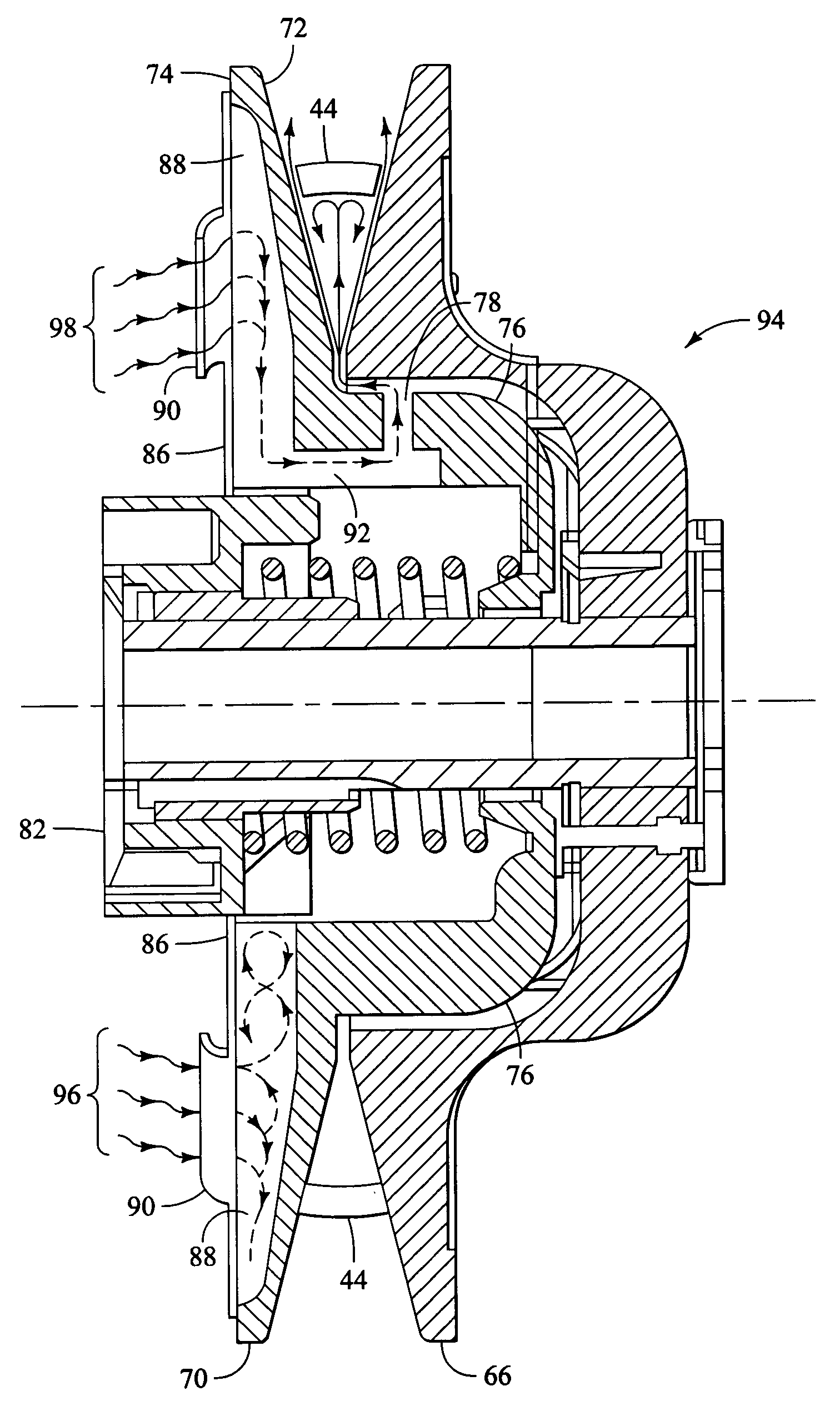
Ventilated clutch having exhaust hub
a technology of exhaust hub and clutch, which is applied in the direction of mechanical actuated clutches, gearing, hoisting equipment, etc., can solve the problems of belt breaking, belt breaking, belt breaking, etc., and achieves the effect of reducing belt slippag
- Summary
- Abstract
- Description
- Claims
- Application Information
AI Technical Summary
Benefits of technology
Problems solved by technology
Method used
Image

Examples
Embodiment Construction
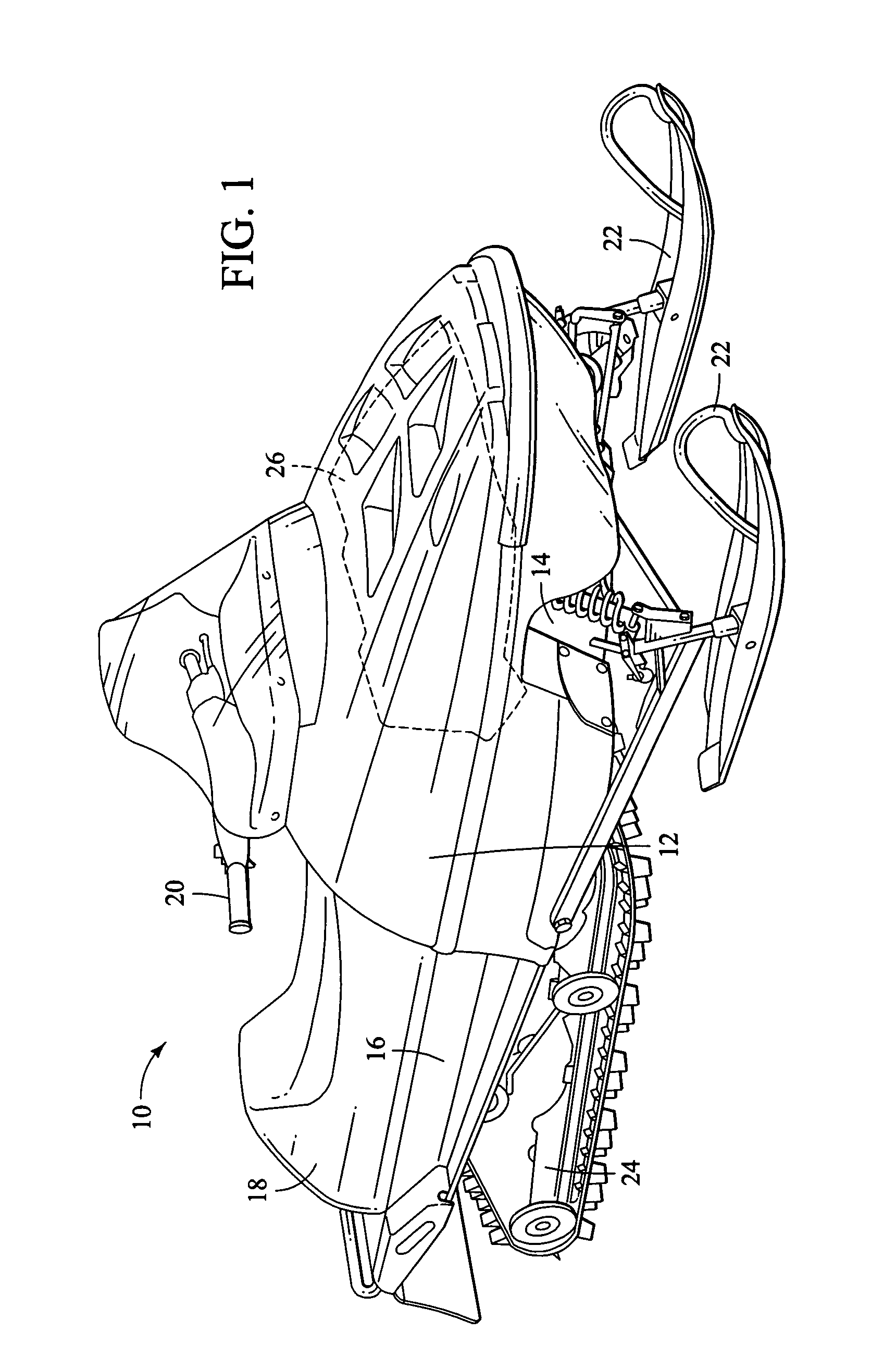
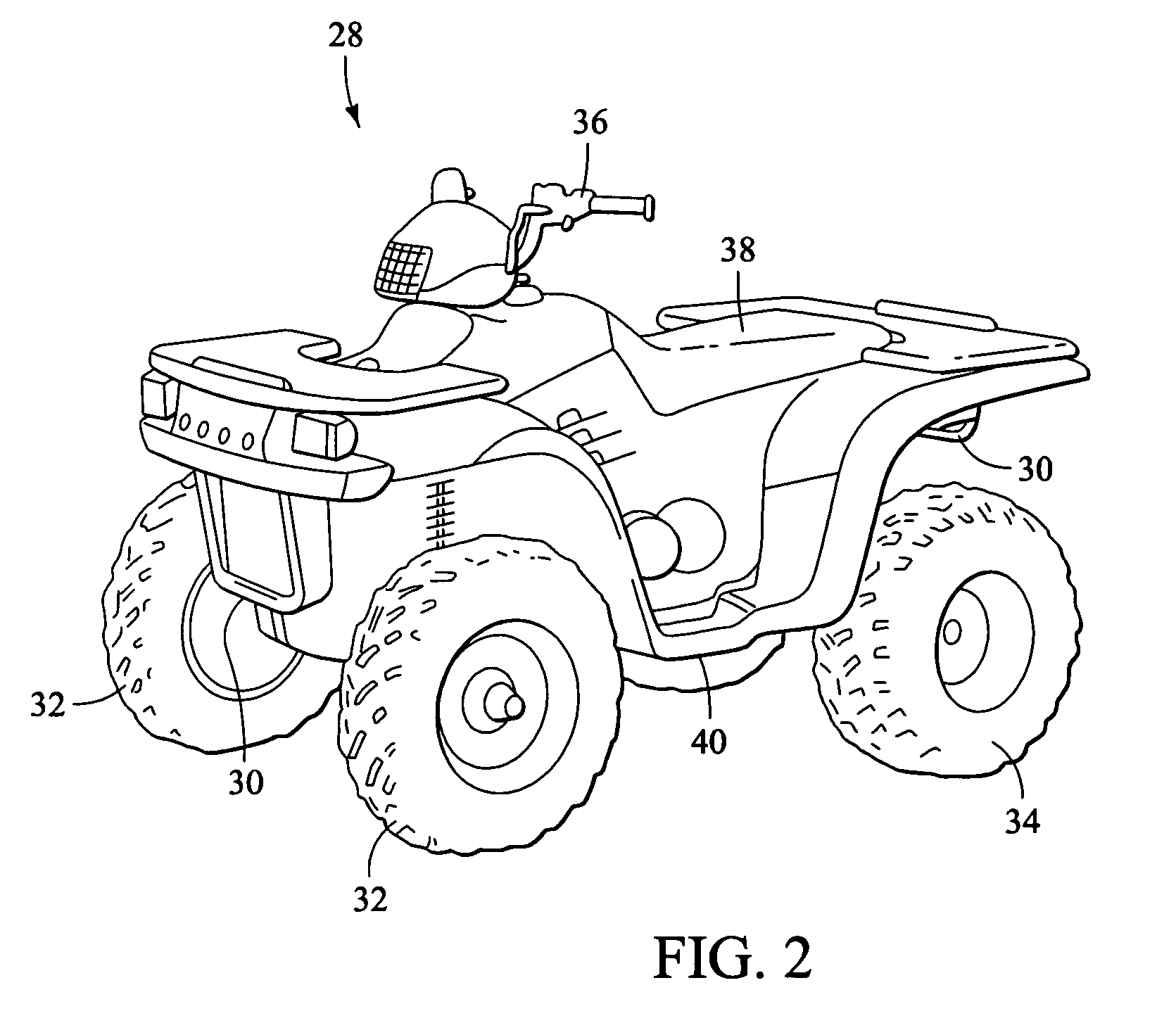
[0017]The following detailed description is to be read with reference to the drawings, in which like elements in different figures have like reference numerals. The drawings, which are not necessarily to scale, depict selected embodiments, but are not intended to limit the scope of the invention. It will be understood that many of the specific details of the vehicle incorporating the system illustrated in the drawings could be changed or modified by one of ordinary skill in the art without departing significantly from the spirit of the invention. The function and operation of continuously variable transmissions (CVTs) are well known (see e.g., U.S. Pat. No. 3,861,229, Domaas, the teachings of which are incorporated herein by reference) and need not be described in detail. The CVT of the invention is designed for use on vehicles such as snowmobiles and ATVs, however it may be used on such other vehicles as golf carts and the like.
[0018]A snowmobile 10 having a system in accordance wi...
PUM
 Abstract
Description
Claims
Application Information