Battery state monitoring circuit and battery device

a battery state monitoring and circuit technology, applied in safety/protection circuits, secondary cells servicing/maintenance, electrochemical generators, etc., can solve problems such as shortened battery life and shift of detection voltag

Active Publication Date: 2005-09-06
ABLIC INC
View PDF4 Cites 9 Cited by
  • Summary
  • Abstract
  • Description
  • Claims
  • Application Information

AI Technical Summary

Benefits of technology

[0007]Therefore, an object of the present invention is to solve the above-mentioned conventional problems and to realize a battery state monitoring circuit in which detection is reliably made even if a continuous noise is entered, thereby providing a battery device having a long life and safety.

Problems solved by technology

However, when a continuous noise enters the device, the above-mentioned states become hard to be detected, thereby shifting a detection voltage.
In addition, if the over-discharge detection is hard to be effected to shift the detection voltage to a lower voltage, the secondary battery is over-discharged, so that a battery life is shortened.

Method used


Image

  • Battery state monitoring circuit and battery device
  • Battery state monitoring circuit and battery device

Examples


Embodiment Construction

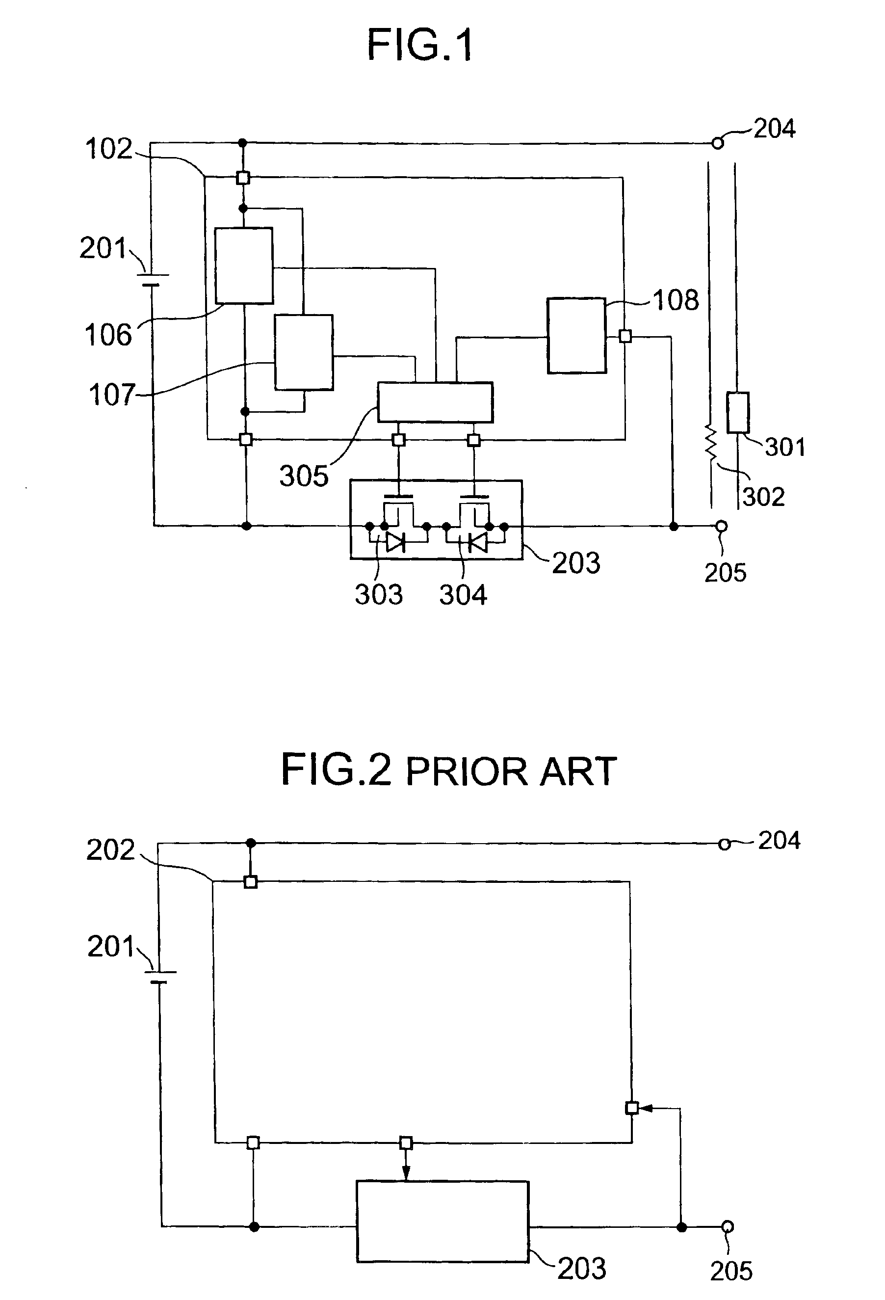
[0035]Hereinafter, an embodiment of the present invention will be described with reference to the drawings. FIG. 1 is a circuit block diagram showing an embodiment of a battery device including a battery state monitoring circuit according to the present invention. As shown in FIG. 1, a battery state monitoring circuit 102 includes an over-charge detecting circuit 106, an over-discharge detecting circuit 107, an over-current detecting circuit 108, and a logic circuit 305.

[0036]A charger 301 is connected between an external terminal +V0204 and an external terminal −V0205 and a charging operation is started. When a voltage of a secondary battery becomes larger than an upper limit voltage to which the secondary battery is charged, a detection signal is outputted from the over-charge detecting circuit 106. In response to the detection signal, the logic circuit 305 outputs a Lo signal to an FET-B 304 in a switch circuit 203 so as to turn off the FET-B 304. On the other hand, when the volt...


PUM

PropertyMeasurementUnit
currentaaaaaaaaaa
voltageaaaaaaaaaa
charge currentaaaaaaaaaa

Abstract

To realize a battery state monitoring circuit in which detection is reliably made even if a continuous noise is entered, and to provide a battery device which has a long life and is safe. In the battery state monitoring circuit, the detecting circuit outputs a signal for controlling a switch circuit in accordance with a state of the secondary battery with respect to one of a specified voltage value and a specified current value. The signal includes one of: a detection signal for starting one of charge protection and discharge protection of the secondary battery; and a release signal for releasing the one of the charge protection and the discharge protection of the secondary battery. A switching rate from the release signal to the detection signal is higher than a switching rate from the detection signal to the release signal.

Description

BACKGROUND OF THE INVENTION[0001]1. Field of the Invention[0002]The present invention relates to a battery state monitoring circuit capable of controlling a charging / discharging operation of a secondary battery and a battery device using the circuit.[0003]2. Description of the Related Art[0004]A power supply device shown in a circuit block diagram of FIG. 2 has been known as a conventional battery device composed of a secondary battery. That is, a secondary battery 201 is connected with an external terminal −V0205 or +V0204 through a switch circuit 203 which is a current limiting unit. Further, a battery state monitoring circuit 202 is connected in parallel with the secondary battery 201. The battery state monitoring circuit 202 has a function for detecting a voltage and a current of the secondary battery 201. In any of: an over-charge state in which the secondary battery 201 has a voltage value higher than a predetermined voltage value; an over-discharge state in which the secondar...

Claims


Application Information

Patent Timeline
Patent Type & Authority Patents(United States)
IPC IPC(8): H02J7/00H01M10/44H02J7/04H02J7/10
CPCH02J7/0031H02J2007/004H02J2007/0037H02J7/00302H02J7/00306H02J7/04
Inventor SAKURAI, ATSUSHI
Owner ABLIC INC
Why Eureka
Try Eureka