Gain and phase balanced amplifier redundancy system

a phase balanced, amplifier technology, applied in amplifiers with coupling networks, amplifier protection circuit arrangements, semiconductor devices/discharge tubes, etc., can solve the problems of degrading payload performance, changing antenna patterns, and still introducing differences in line length, so as to reduce or maintain power requirements, reduce signal degradation, and equalize line length differences

a phase balanced, amplifier technology, applied in amplifiers with coupling networks, amplifier protection circuit arrangements, semiconductor devices/discharge tubes, etc., can solve the problems of degrading payload performance, changing antenna patterns, and still introducing differences in line length, so as to reduce or maintain power requirements, reduce signal degradation, and equalize line length differences

US6943625B2Active Publication Date: 2005-09-13THE BOEING CO

Image

  • Gain and phase balanced amplifier redundancy system
  • Gain and phase balanced amplifier redundancy system
  • Gain and phase balanced amplifier redundancy system

Examples


Embodiment Construction

[0026]The present invention is illustrated with respect to a gain and phase balanced amplifier redundancy system, particularly suited to the satellite communications field. The present invention is, however, applicable to various other uses that may require amplifier redundancy systems, as will be understood by one skilled in the art.

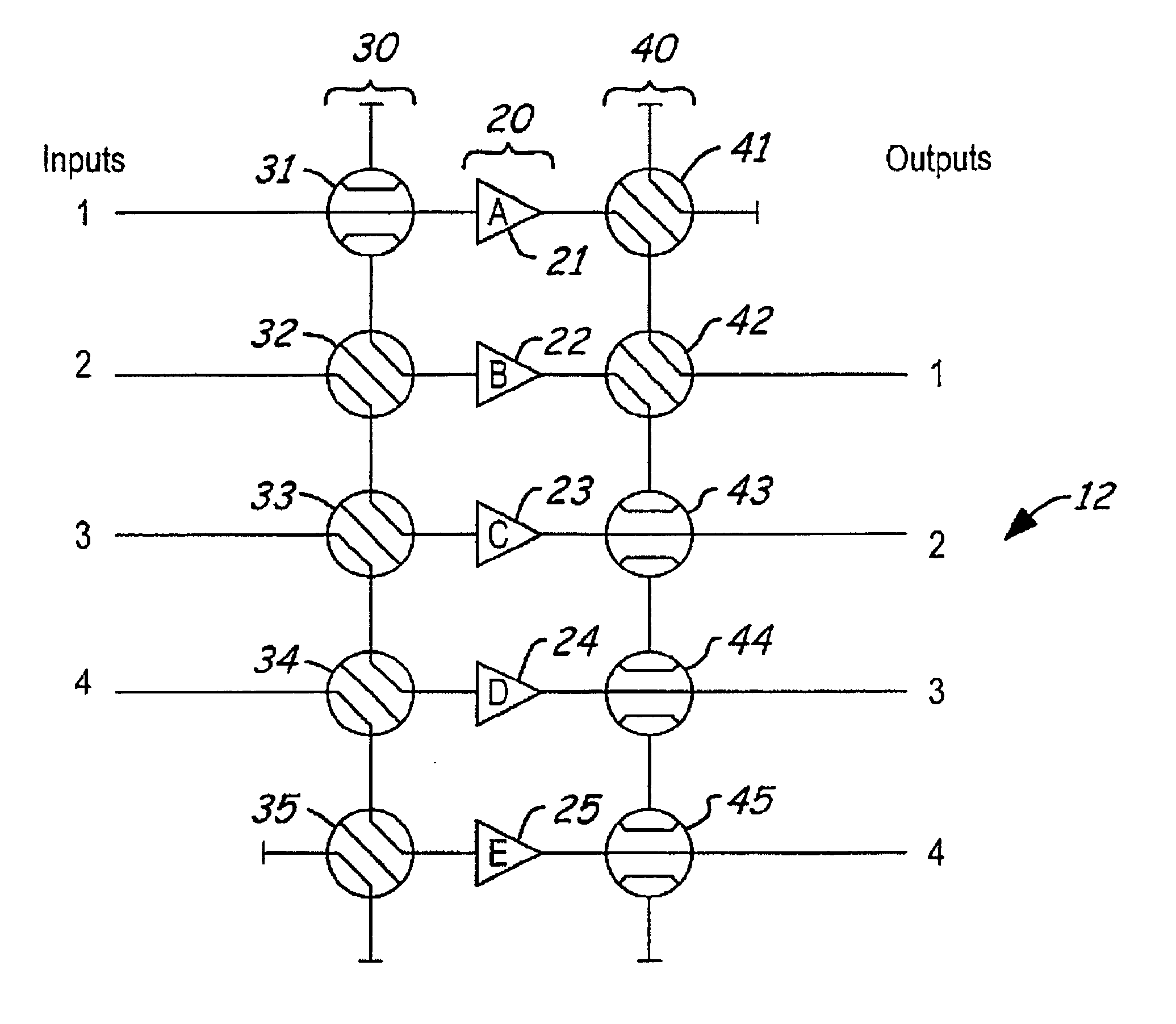
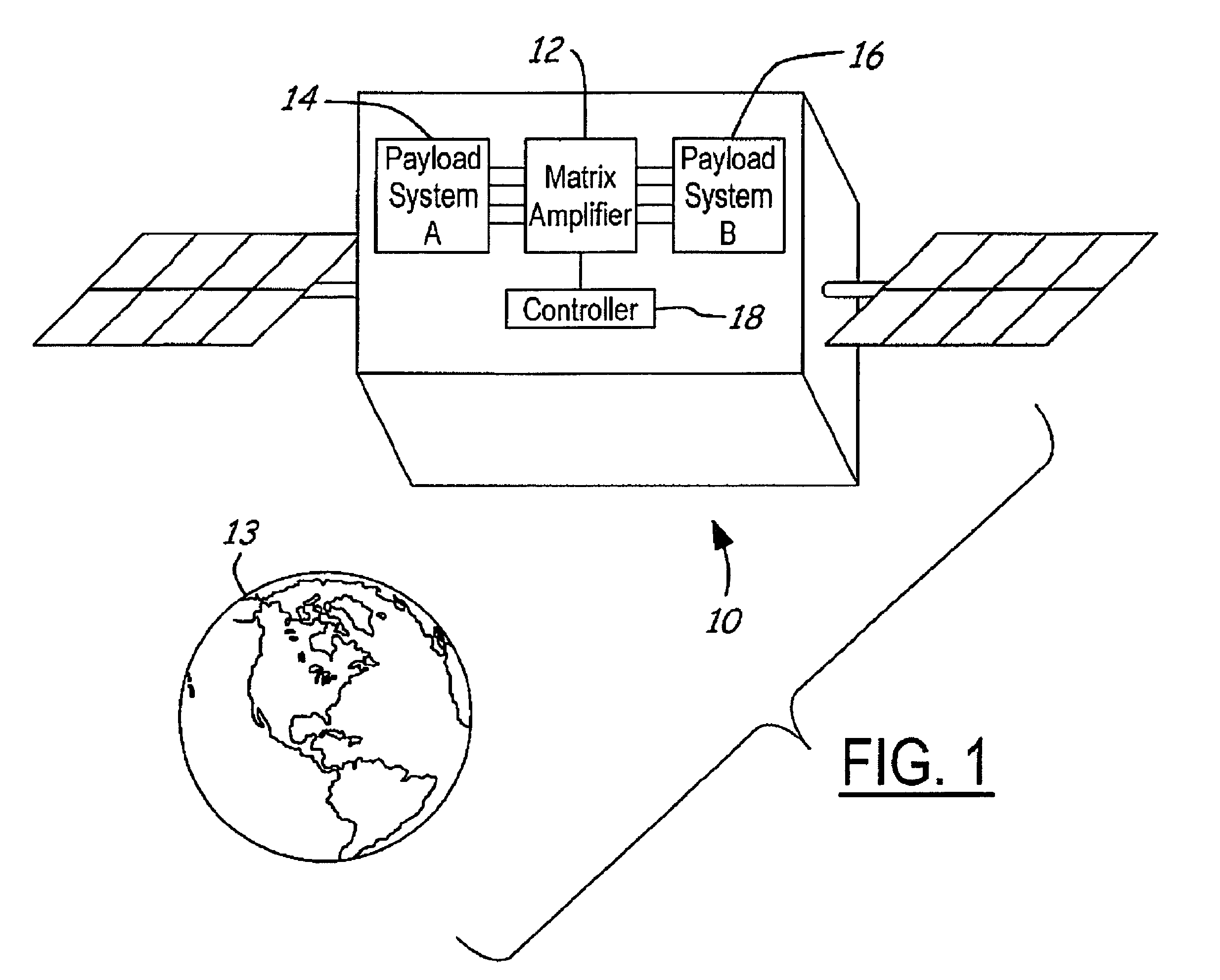
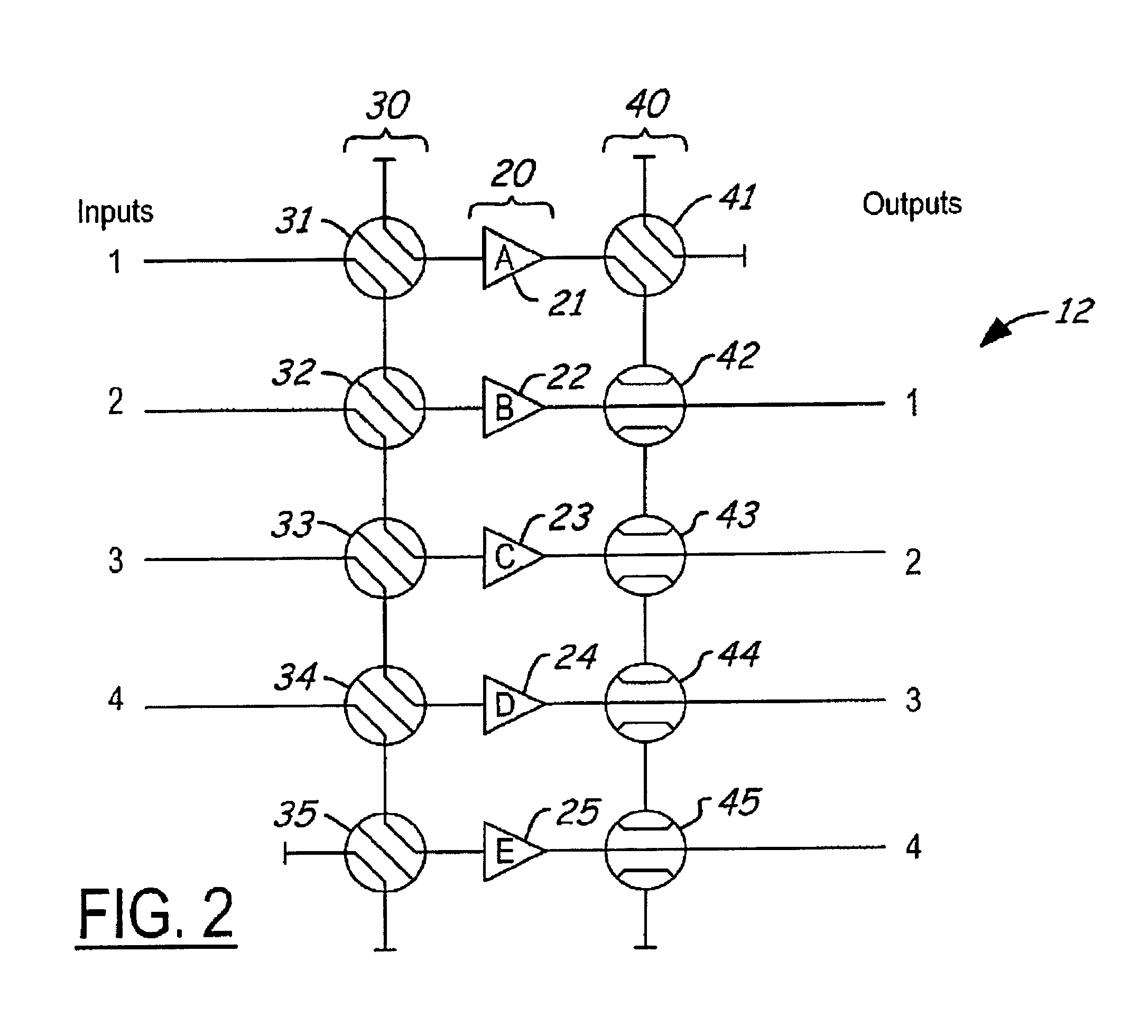
[0027]Referring to FIGS. 1 and 2, the communications system 10, including an amplifier redundancy system 12 is illustrated. The aerospace system 10 is merely an illustrative example of a satellite payload orbiting the earth 13 wherein the amplifier redundancy system 12 would be beneficial and is not meant to be limiting, as will be understood by one skilled in the art.

[0028]The amplifier redundancy system 12 will typically receive inputs from a payload system 14, such as a set of upconverters or switches, amplify the signals, and then generate outputs which will typically be received by an additional payload system 16, such as an antenna, as will be und...


PUM


Abstract

An amplifier redundancy system includes an amplifier receiving signals from a first input switch when the switch is in a side port position. The system further includes a first output switch, in a side port position, receiving signals from the amplifier. A second amplifier receives signals from the first input switch through a second input switch and generates amplified signals therefrom. The second input switch also receives signals from the first input switch when the first input switch is in the side port position. The first input switch is initially in the side port position but switches to a through port position in response to a failure in the second amplifier. A second output switch is in a through port position and switches to a side port position and receives signals through the first output switch in response to the failure in the second amplifier.

Description

BACKGROUND OF INVENTION[0001]The present invention relates generally to amplifier redundancy systems, and more particularly, to a gain and phase balanced amplifier redundancy system suitable for use in satellite communications payloads.[0002]A typical satellite communications payload includes an output section that may contain multiple amplifiers. These amplifiers are sometimes configured such that satellite communications signals, intended for a user on the ground, pass through more than one amplifier to generate a large amount of output power (more than is capable of being delivered by a single amplifier). This type of system is sometimes referred to as a matrix amplifier system.[0003]For matrix amplifier systems, the phase and amplitude of the signals passing through each amplifier path are significant because these signals combine with a specific phase to achieve a power distribution among satellite antenna radiating elements, which is required to obtain a proper antenna pattern...

Claims


Application Information

Patent Timeline
13 Sep 2005
Publication
US6943625B2
IPC
H03F3/68; H03F1/52; H03F3/60
CPC
H03F1/526; H03F3/602
Inventors
LANE, STEVEN O.; SLEIGHT, BRIAN T.