Method and apparatus to control modular asynchronous contactors

a technology of modular contactors and contactor parts, applied in emergency protective circuit arrangements, electromagnetic relay details, relays, etc., can solve the problems of composite materials being expensive, and affecting the manufacturing efficiency of contactors

Inactive Publication Date: 2005-09-13
EATON CORP
View PDF23 Cites 52 Cited by
  • Summary
  • Abstract
  • Description
  • Claims
  • Application Information

AI Technical Summary

Benefits of technology

[0008]The present invention provides a method and apparatus of independently controlling contactors of a modular contactor assembly overcoming the aforementioned drawbacks and provides a control scheme that is applicable therewith. The contactor assembly includes a contactor for each phase or pole of an electrical device. The contactor assembly is applicable as both a switching device and an isolation or load protection device. As such, each contactor is constructed so that each includes multiple contact assemblies. Moreover, the contactors within a single contactor assembly or housing can be independently controlled so that the contacts of one contactor can be opened without opening the contacts of the other contactors in the contactor assembly.

Problems solved by technology

This contactor construction has some drawbacks, particularly in high power applications.
These composite materials can be expensive and contribute to increased manufacturing costs of the contactor.
Other contactors have been designed with complex biasing mechanisms to regulate “blow open” of the contacts under variable fault conditions, but the biasing mechanisms also add to the complexity and cost of the contactor.
Increasing the size of the contact elements, however, requires larger actuating mechanisms, coils, biasing springs, and the like, which all lead to increased product size and increased manufacturing costs.
Additionally, a contactor wherein all the contact assemblies open in unison can result in contact erosion as a result of arcs forming between the contacts during breaking.
When all the contact assemblies or sets of contacts are controlled in unison, a detected abnormal condition, such as a fault condition, in any phase of the three-phase input causes all the contact assemblies to break open because the contact assemblies share a bridge or crossbar.
As a result, the contacts may open at non-ideal current conditions.
This non-zero opening can cause arcing between the contact elements of the second and third contact assemblies causing contact erosion that can lead to premature failure of the contactor.

Method used


Image

  • Method and apparatus to control modular asynchronous contactors
  • Method and apparatus to control modular asynchronous contactors
  • Method and apparatus to control modular asynchronous contactors

Examples


Embodiment Construction

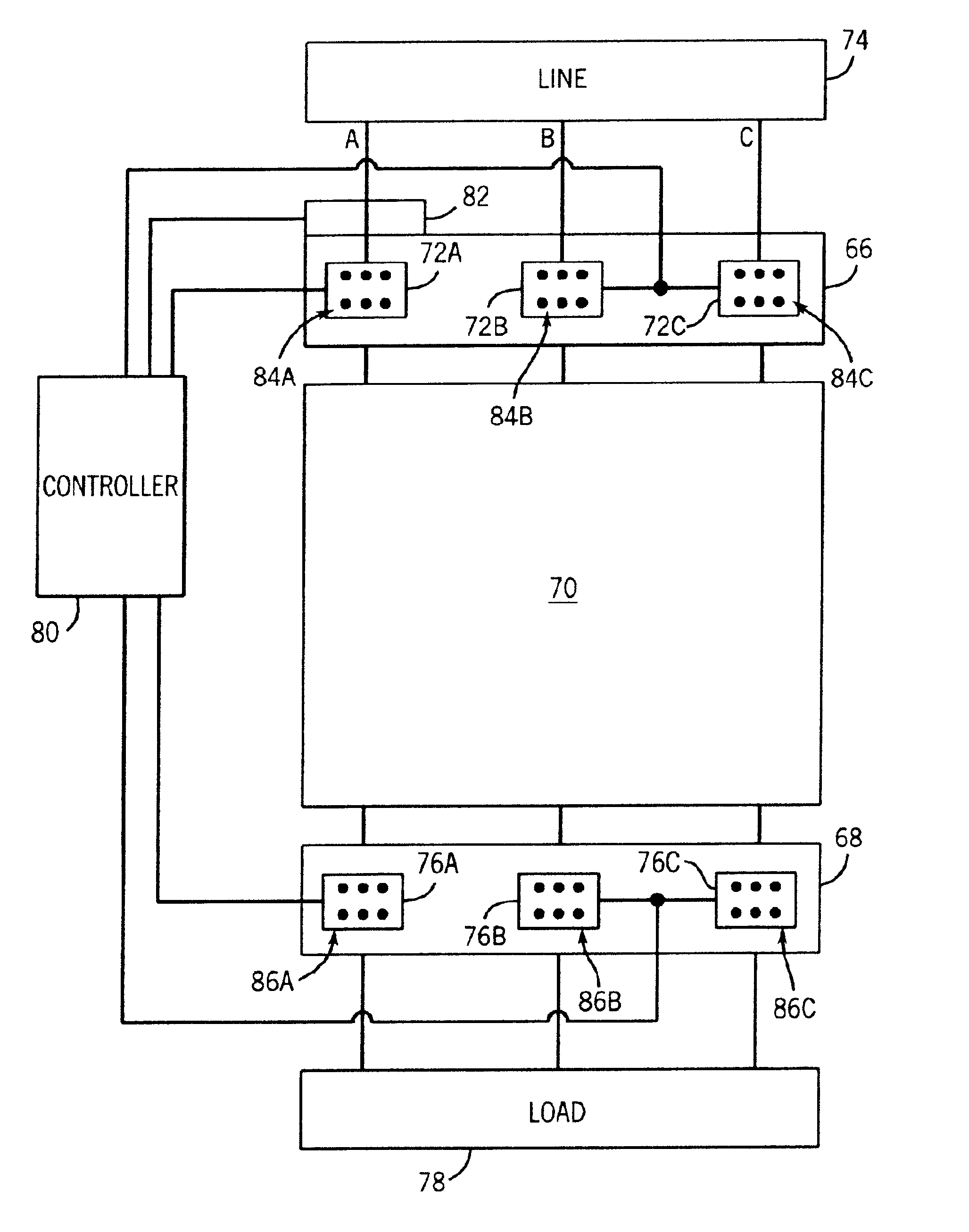
[0032]The present invention will be described with respect to an electromagnetic contactor assembly for use in starter applications such as, the switching on / off of a load as well as to protect a load, such as a motor, from current overload. The electromagnetic contactor assembly and controls of the present invention are equivalently applicable to heating load contactor assemblies, on-demand modular contactor assemblies, modular large frame contactor assemblies, and the like. The present invention is also applicable with other types of contactor assemblies where it is desirable to reduce contact erosion resulting from arcs during breaking and bounce arcs during making of the contacts. Additionally, the present invention will be described with respect to implementation with a three-phase electrical device; however, the present invention is equivalently applicable with other electrical devices.

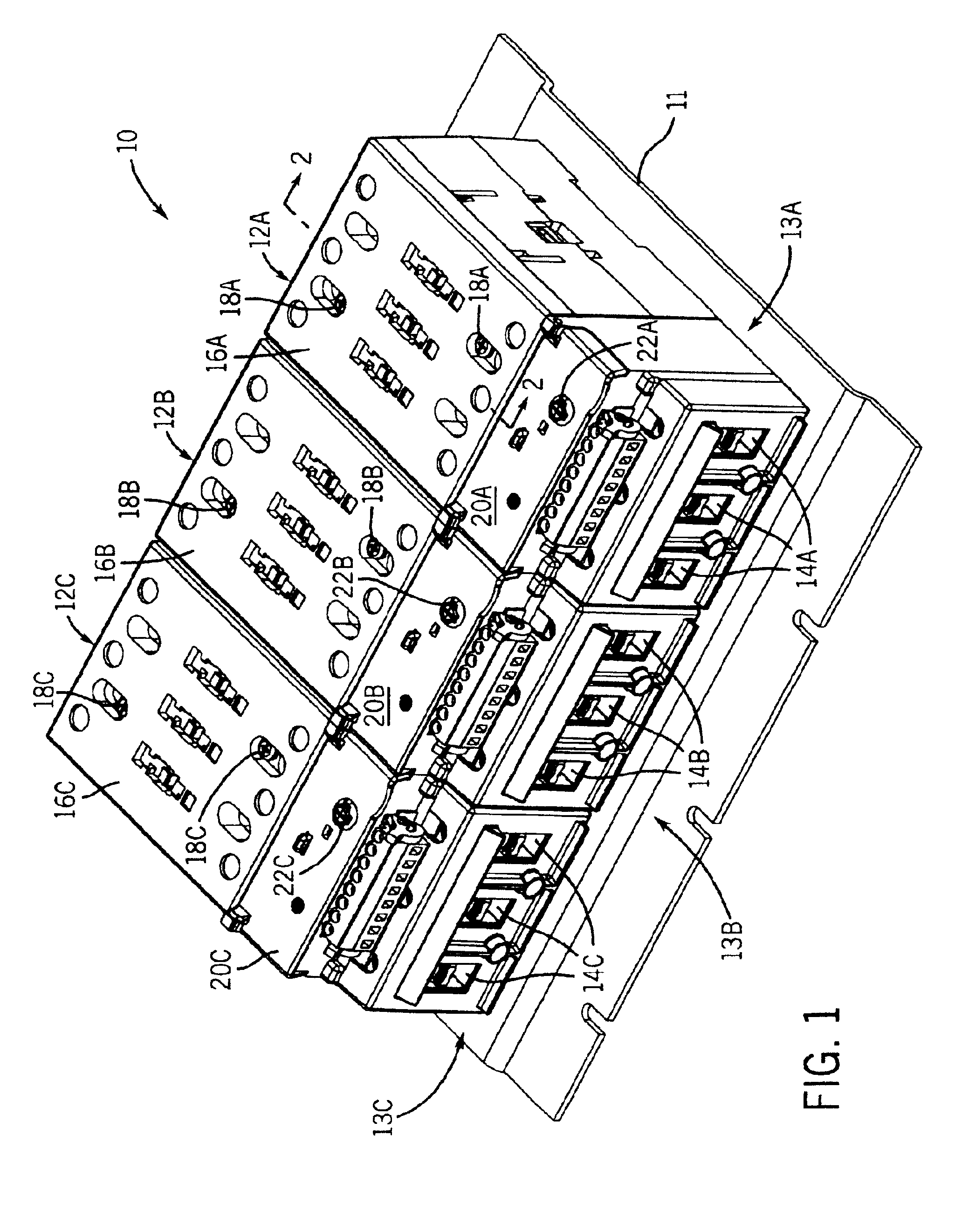
[0033]Referring now to FIG. 1, a modular contactor assembly 10 is shown in perspective view....


PUM


Abstract

A modular asynchronous contactor assembly includes a contactor for each phase or pole of an electrical device. The contactor assembly is applicable as both a switching device and an isolation or load protection device. As such, each contactor is constructed so that each includes multiple contact assemblies. Moreover, the contactors within a single contactor assembly or housing can be independently controlled so that the contacts of one contactor can be opened without opening the contacts of the other contactors of the contactor assembly.

Description

CROSS-REFERENCE TO RELATED APPLICATIONS[0001]The present invention is a continuation and claims priority of allowed U.S. patent application Ser. No. 10 / 248,916 entitled, “Method and Apparatus to Control Modular Asynchronous Contactors”, and filed Feb. 28, 2003.BACKGROUND OF THE INVENTION[0002]The present invention relates generally to an electrical switching device, and more particularly, to a method and apparatus of independently controlling contactors of a modular contactor assembly.[0003]Typically, contactors are used in starter applications to switch on / off a load as well as to protect a load, such as a motor, or other electrical devices from current overloading. As such, a typical contactor will have three contact assemblies; a contact assembly for each phase or pole of a three-phase electrical device. Each contact assembly typically includes a pair of stationary contacts and a moveable contact. One stationary contact will be a line side contact and the other stationary contact...

Claims


Application Information

Patent Timeline
Patent Type & Authority Patents(United States)
IPC IPC(8): H01H50/54H01H9/54H01H9/56H01H9/40H01H9/30
CPCH01H9/563H01H50/546H01H9/40H01H50/002
Inventor ZHOU, XINLITTLE, MICHAEL T.KINSELLA, JAMESWIELOCH, CHRISHETZMANNSEDER, ENGELBERT
Owner EATON CORP
Why Eureka
Try Eureka