Adjustable template

a template and adjustable technology, applied in the field of geological instruments, can solve the problems of inability to use the template for those openings and other templates, inconvenient and expensive, and currently available templates, and achieve the effect of accurate and precise marks

Active Publication Date: 2005-09-20
EASTER TERRY L +1
View PDF19 Cites 11 Cited by
  • Summary
  • Abstract
  • Description
  • Claims
  • Application Information

AI Technical Summary

Benefits of technology

[0013]It is another object of the present invention to provide an adjustable template that is durable and re-usable.
[0017]Using the template embodying the present invention will permit a worker to adjust the template to the exact application and to obtain accurate and precise marks for the task at hand. The template is durable and thus is re-usable and is very adaptable to a wide variety of tasks whereby a single tool can be used for a wide variety of applications.

Problems solved by technology

For example, the presently available templates of which the inventor is aware, are not adjustable.
If other openings, or other sized or shaped openings are required, the template cannot be used for those openings and other templates are required.
This is inconvenient and expensive.
Still further, some of the templates of which the inventor is aware are not durable and some may not even be re-usable.
This also requires a worker to have several templates which is also inconvenient and expensive, Therefore, there is a need for an adjustable template that is durable and re-usable.
Many of the templates of which the inventor is aware are not as accurate as possible.
A skilled worker can account for this, but some less skilled workers may have difficulty and the final product may not be as finished as possible.
If the template is not securely held in place, the marked area may not be in a desired location.
However, this may be difficult if the template is not durable and easily held in place.

Method used


Image

  • Adjustable template
  • Adjustable template

Examples


Embodiment Construction

[0022]Other objects, features and advantages of the invention will become apparent from a consideration of the following detailed description and the accompanying drawings.

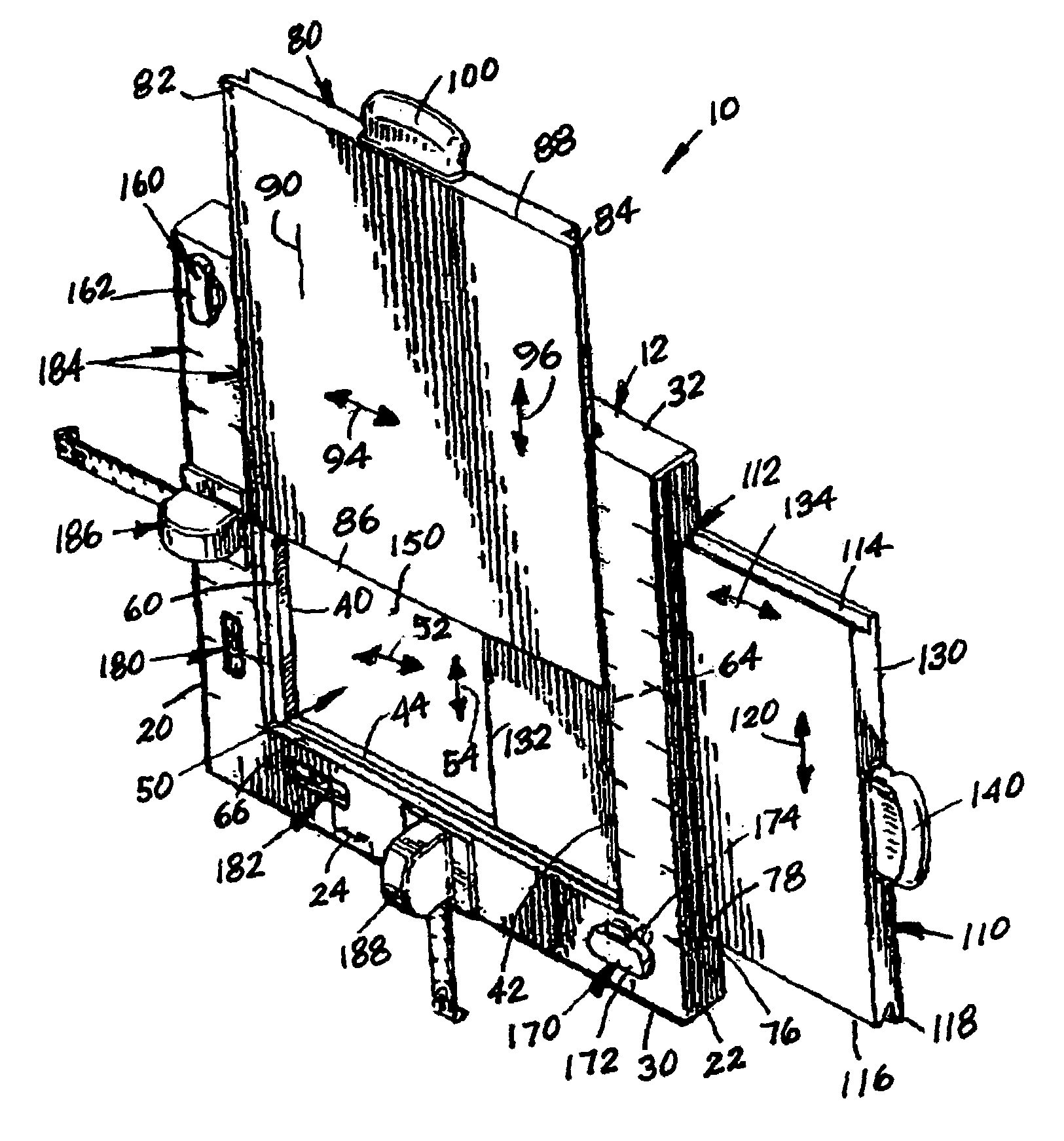
[0023]Referring to the Figures, it can be understood that the present invention is embodied in an adjustable template 10. Adjustable template 10 comprises a base 12 which includes a first surface 14 that is a front surface when base 12 is in a use orientation such as shown in FIG. 1. Base 12 further includes a second surface 16 that is a rear surface when base 12 is in a use orientation. A thickness dimension 18 extends between first surface 14 and second surface 16.

[0024]Base 12 further includes a first side edge 20, a second side edge 22, and a width dimension 24 which extends between first side edge 20 and second side edge 22.

[0025]Base 12 further includes a first end edge 30, a second end edge 32, and a longitudinal dimension 34 which extends between first end edge 30 and second end edge 32.

[0026]A first insid...


PUM


Abstract

A template includes a base on which a plurality of wings are slidably mounted to move with respect to each other. The base also includes locks for locking the wings in positions. Levels, tape measures and markings are also on the base to assist with placement of the template.

Description

BACKGROUND OF THE INVENTION[0001]1. Field of the Invention[0002]The present invention relates to the general art of geometric instruments, and to the particular field of gauges and templates.[0003]2. Discussion of the Related Art[0004]Many construction projects require cutting specifically sized and located holes in a substrate. For example, placing electrical outlets, electrical switches, and the like require specifically sized and located holes. Further examples include pipe outlets, conduit outlets and the like.[0005]While the art contains many examples of templates, most of these templates have several drawbacks. For example, the presently available templates of which the inventor is aware, are not adjustable. That is, a template is specifically sized for a specific application, such as defining an opening for an electrical outlet, or the like. If other openings, or other sized or shaped openings are required, the template cannot be used for those openings and other templates ar...

Claims


Application Information

Patent Timeline
IPC IPC(8): G01B3/14
CPCG01B3/14H02G1/00H02G3/00H02G2200/30
Inventor EASTER, TERRY L.EASTER, JANET F.
Owner EASTER TERRY L
Why Eureka
Try Eureka