Traveling wave, multiplying D/A converter

a converter and travel wave technology, applied in the field of multiplication of digital to analog converters, can solve the problems of limiting the design and deployment of such systems, limiting the bandwidth, and the resolution of microwave or millimeter wave frequencies, and limiting the bandwidth, so as to reduce the requirements for timing and component matching, size and cost, and the effect of reducing power consumption

Active Publication Date: 2005-10-04
THE BOEING CO
View PDF5 Cites 11 Cited by
  • Summary
  • Abstract
  • Description
  • Claims
  • Application Information

AI Technical Summary

Benefits of technology

[0014]There is a need in the art for RF transceivers with reduced power consumption, size, and cost that incorporate a single element which accepts digital data as an input and directly produces a modulated RF output for transmission via an antenna at microwave and millimeter wave frequencies with the resolutions, bandwidths, and tuning characteristics that are all simultaneously needed in broadband communications systems. There is also a need in the art to provide such direct modulation at microwave and millimeter wave frequencies with significant reductions in the requirements for timing and component matching.

Problems solved by technology

While conventional superheterodyne architectures (e.g., a transceiver that uses a local oscillator to up-convert a baseband signal for modulation of an RF carrier) have yielded excellent performance in a wide range of RF transceivers, the power consumption, size, and cost of such systems have often been limiting factors in their design and deployment.
Although a number of “bits-to-RF” direct synthesis approaches have previously been implemented, these techniques have not been able to reach microwave or millimeter wave frequencies with the resolutions, bandwidths, and tuning characteristics that are all simultaneously needed in broadband communications systems.
The shifting operation will limit the bandwidth, and the impedance properties of the single-ended design limit the achievable RF frequency and resolution (e.g., number of bits in a data word).
Requiring a HEMT or MESFET technology will limit the attainable resolution, and the RC (resistance-capacitance) time constants associated with resistor ladders inhibit the realizable data rates (e.g., adversely affecting bandwidth).

Method used


Image

  • Traveling wave, multiplying D/A converter
  • Traveling wave, multiplying D/A converter
  • Traveling wave, multiplying D/A converter

Examples


Embodiment Construction

[0023]The following detailed description is of the best currently contemplated modes of carrying out the invention. The description is not to be taken in a limiting sense, but is made merely for the purpose of illustrating the general principles of the invention, since the scope of the invention is best defined by the appended claims.

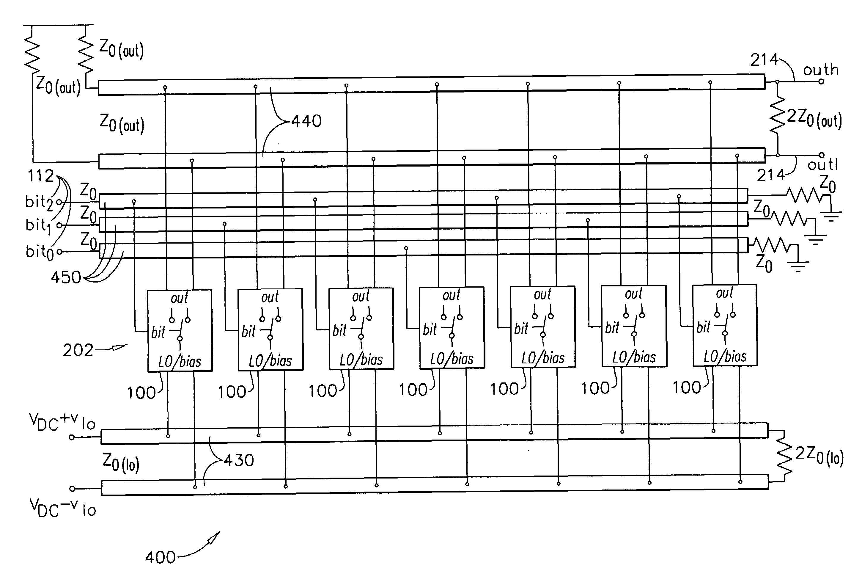
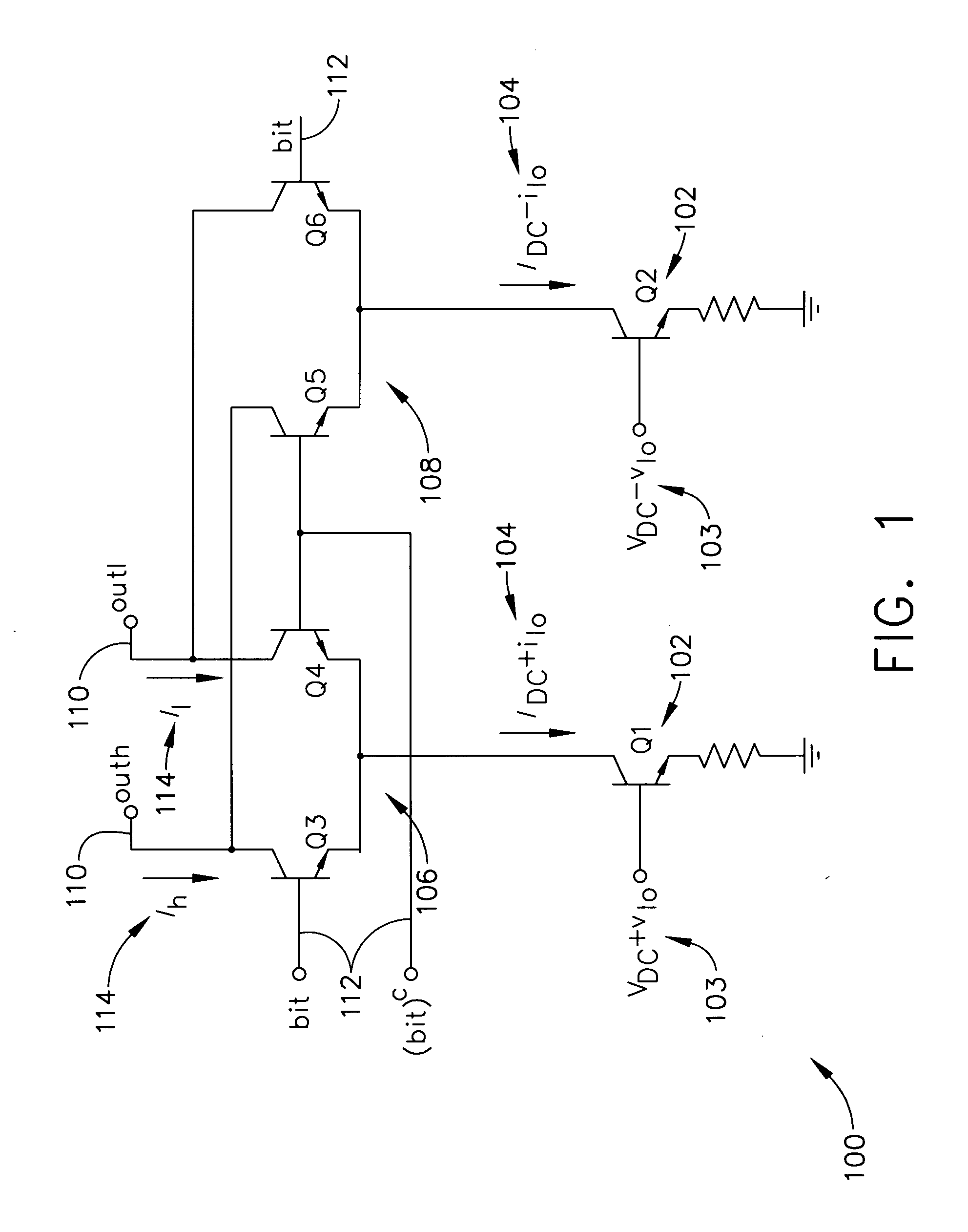
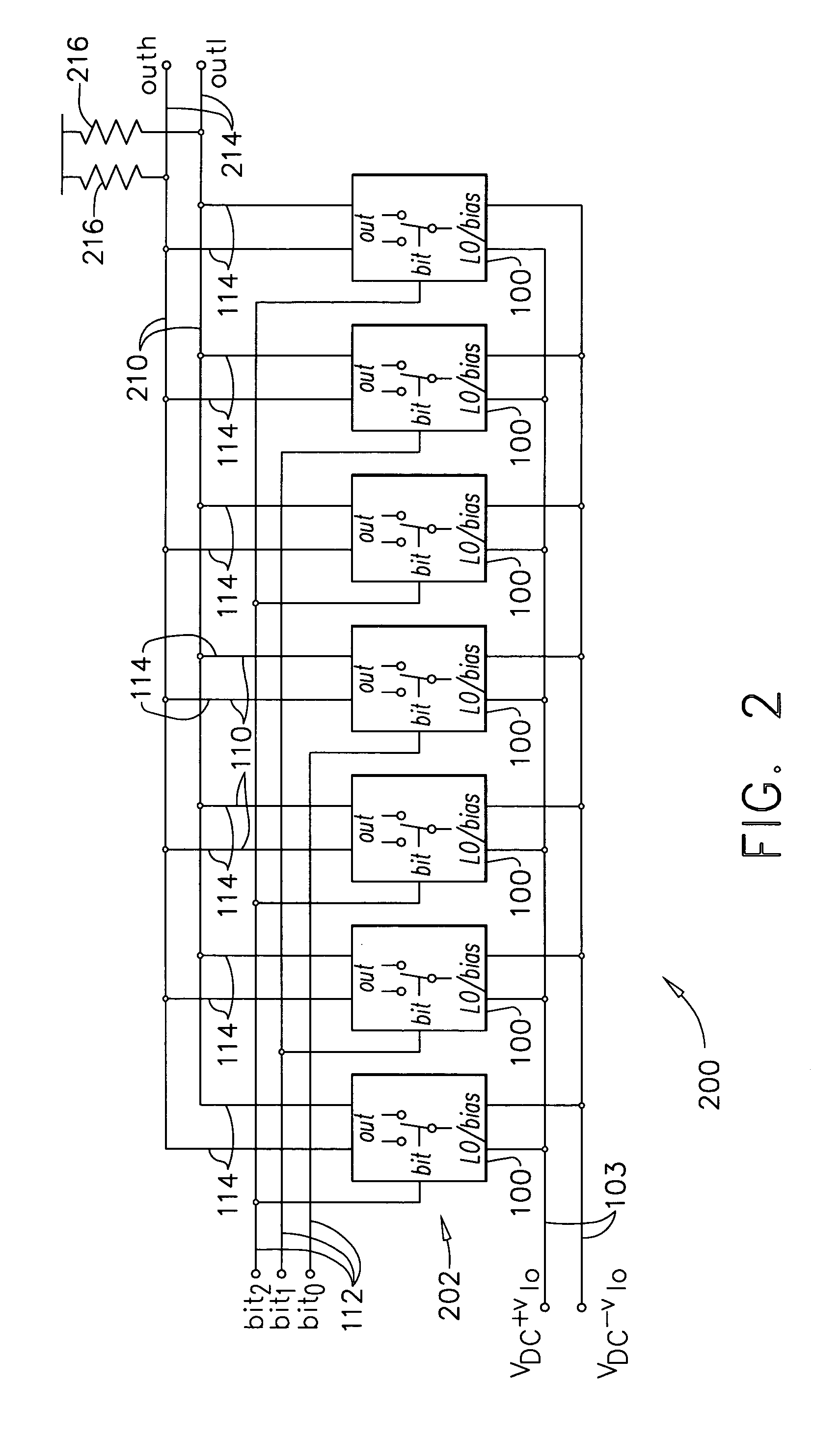
[0024]Broadly, one embodiment of the present invention provides a direct “bits-to-RF” digital-to-analog (D / A) converter architecture that supports the synthesis of high bandwidth, digitally modulated waveforms at microwave and millimeter-wave frequencies and above. Direct bits-to-RF D / A converters are useful in communication systems wherever data or synthesized signals are being transmitted—usually wirelessly—including, for example, satellites, television, cell phones, and wireless LAN, and any of these communication systems may employ an embodiment of the present invention. In particular, transceivers incorporating an embodiment of the present inventio...


PUM


Abstract

A traveling wave multiplying digital-to-analog converter has propagation-delay matched transmission lines for conversion of a high data rate digital input to a high frequency RF analog output, for example, at microwave and millimeter wave frequencies and above. The traveling wave multiplying digital-to-analog converter includes an array of constant, high impedance multiplying cells that are identical to improve component matching and propagation delay matching. The multiplying cells are connected in a spatial interleaving manner along bit lines that propagate the high bandwidth digital input. The interleaving effects a “spatial averaging” that maintains linearity of digital to analog conversion in the presence of any linear gradient δ from one cell to another across the array of multiplying cells.

Description

BACKGROUND OF THE INVENTION[0001]The present invention generally relates to synthesis of high bandwidth, digitally modulated waveforms at microwave and millimeter wave frequencies and, more particularly, to a multiplying digital-to-analog converter (DAC) that exploits techniques of distributed amplification, also referred to as traveling wave amplification, to synthesize high resolution radio frequency (RF) signals at microwave and millimeter wave frequencies and above without mixer up-conversion, and with a clock rate that can be much lower than the RF output frequency.[0002]While conventional superheterodyne architectures (e.g., a transceiver that uses a local oscillator to up-convert a baseband signal for modulation of an RF carrier) have yielded excellent performance in a wide range of RF transceivers, the power consumption, size, and cost of such systems have often been limiting factors in their design and deployment. An often cited “holy grail” for RF transceivers is to incorp...

Claims


Application Information

Patent Timeline
Patent Type & Authority Patents(United States)
IPC IPC(8): H03M1/66
CPCH03M1/745
Inventor HITKO, DONALD
Owner THE BOEING CO
Why Eureka
Try Eureka