Stroller
a stroller and folding technology, applied in the field of folding strollers, can solve the problems of accidental unfolding of the folding stroller, the inability to hold the three-fold stroller in a two-folded state,
- Summary
- Abstract
- Description
- Claims
- Application Information
AI Technical Summary
Benefits of technology
Problems solved by technology
Method used
Image
Examples
first embodiment
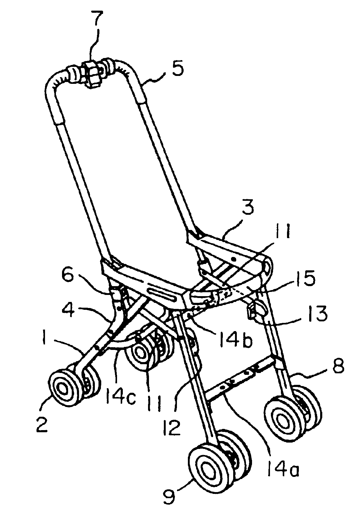
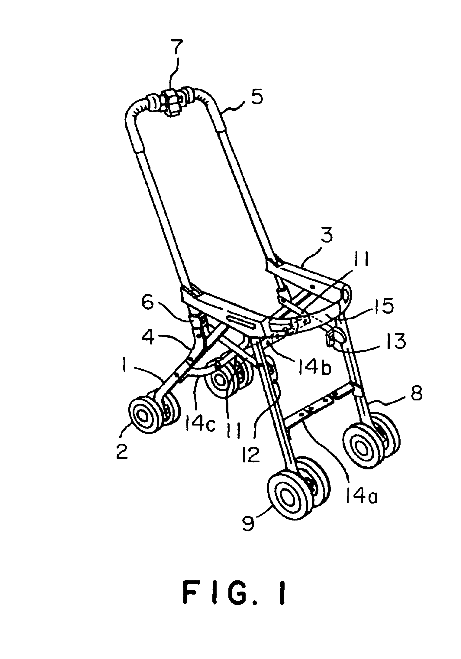
[0033]An outline of a stroller will be explained.
[0034]FIG. 9 is a perspective view of a three-folding stroller in an unfolded state, namely, a working state, and FIG. 10 is a view of the same stroller folded in three, and a locking mechanism included in the stroller. A folding operation for folding the stroller from the unfolded state shown in FIG. 9 in three as shown in FIG. 10 will be described with reference to FIGS. 9 and 10.
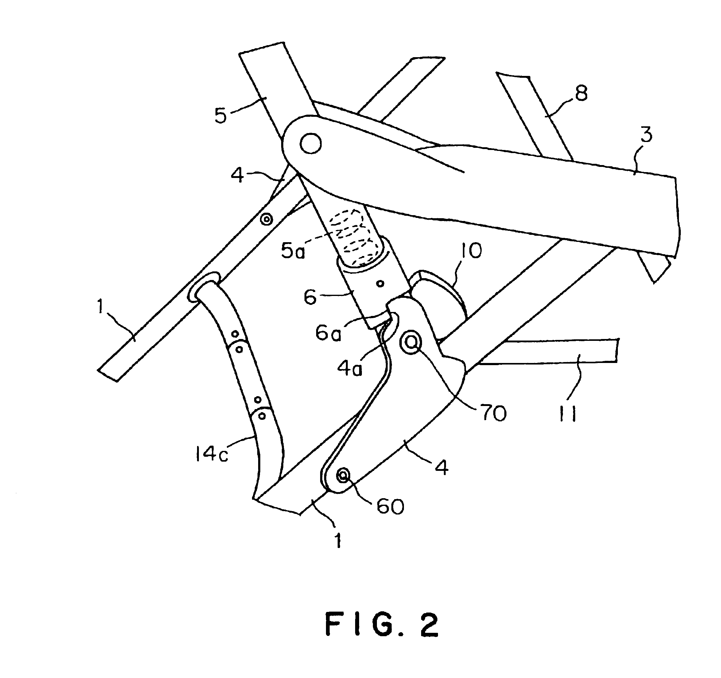
[0035]Referring to FIG. 9, operating wires, not shown, are extended from an operating device 7. Sliders, not shown, are moved by operating the operating wires so as to raise locking members 6 to disengage the locking members 6 from corresponding brackets 4 holding the stroller in an unfolded state, so that the stroller is unlocked.
[0036]Then, the stroller is held by opposite side sections C of a handle 5, front wheels or armrests 3 are raised and turned toward a backrest B as indicated by arrow X (a first folding step). A longitudinal dimension of the strol...
second embodiment
[0059]A stroller of a second embodiment according to the present invention will be described with reference to FIGS. 11 and 12. FIG. 12 is a partly cutaway perspective view of a stroller provided with a suspended seat. The stroller has a body including right and left front legs 112 provided with front wheels 111, right and left rear legs 114 provided with rear wheels 113, a substantially U-shaped handle 115, and right and left armrests 116. A detachable guard 117 is extended between the armrests 116. The handle 115 has right and left side pipes 118. Rear ends of the armrests 116 are joined pivotally to parts of the side pipes 118 near lower ends of the same. Upper ends of the front legs 112 are joined pivotally to front ends of the armrests 116, respectively. Upper ends of the rear legs 114 are joined pivotally to middle parts of the armrests 116, respectively. Lower ends of L-shaped brackets 119 are joined pivotally to middle parts of the rear legs 114, respectively. Lower ends of ...
PUM
 Abstract
Description
Claims
Application Information
 - R&D
- Intellectual Property
- Life Sciences
- Materials
- Tech Scout
- Unparalleled Data Quality
- Higher Quality Content
- 60% Fewer Hallucinations
Browse by: Latest US Patents, China's latest patents, Technical Efficacy Thesaurus, Application Domain, Technology Topic, Popular Technical Reports.
© 2025 PatSnap. All rights reserved.Legal|Privacy policy|Modern Slavery Act Transparency Statement|Sitemap|About US| Contact US: help@patsnap.com


