Display orientation adjustment apparatus

a technology for adjusting apparatus and display, which is applied in the direction of electrical apparatus casings/cabinets/drawers, identification means, instruments, etc., can solve problems such as the rupture of the proximal portion of the projection b>133/b>, and the possibility of encountering problems

Inactive Publication Date: 2005-11-22
NEC DISPLAY SOLUTIONS LTD
View PDF17 Cites 67 Cited by
  • Summary
  • Abstract
  • Description
  • Claims
  • Application Information

AI Technical Summary

Benefits of technology

[0017]According to the above display orientation adjustment apparatus, when the pivotal motion of the movable part in a plane containing a screen of the display (i.e., about an axis substantially perpendicular to the screen) is impeded by the stopper, to be more specific, when the movable part comes to a limit of the restricted range of the pivotal motion, a pivoting force of the predetermined magnitude or greater acting on the stopper would release the impeded state of the stopper, allowing the movable part to pivot beyond the restricted range, so that the excessive pivoting force as above would never concentrate on the components such as the movable part and the stopper, thus preventing breakage thereof.
[0028]Since the movable part of the above display orientation adjustment apparatus has a sliding surface shaped like a spherical zone, the movable part can not only be pivoted about an axis substantially perpendicular to a screen of the display (i.e., in a plane containing the screen), but also be tilted (about a horizontal axis with the top and bottom of the display moved frontward and rearward), and swiveled (about a vertical axis with the right and left sides of the display moved frontward and rearward). Consequently, the display can acquire an increased degree of flexibility in adjustment of its orientation.

Problems solved by technology

However, normal use situations aside, in cases where the display D is inadvertently pivoted beyond the pivotable range, all the pivoting force concentrate on the projection 133 of the support cap 130, which could disadvantageously cause a proximal portion of the projection 133 to rupture as the case may be.
The disadvantageous situation as described above involves a common problem that could be encountered not only in the illustrated orientation adjustment apparatus but also in any other orientation adjustment apparatuses capable of pivoting a display in a plane containing a screen thereof.

Method used


Image

  • Display orientation adjustment apparatus
  • Display orientation adjustment apparatus
  • Display orientation adjustment apparatus

Examples


first embodiment

[First Embodiment]

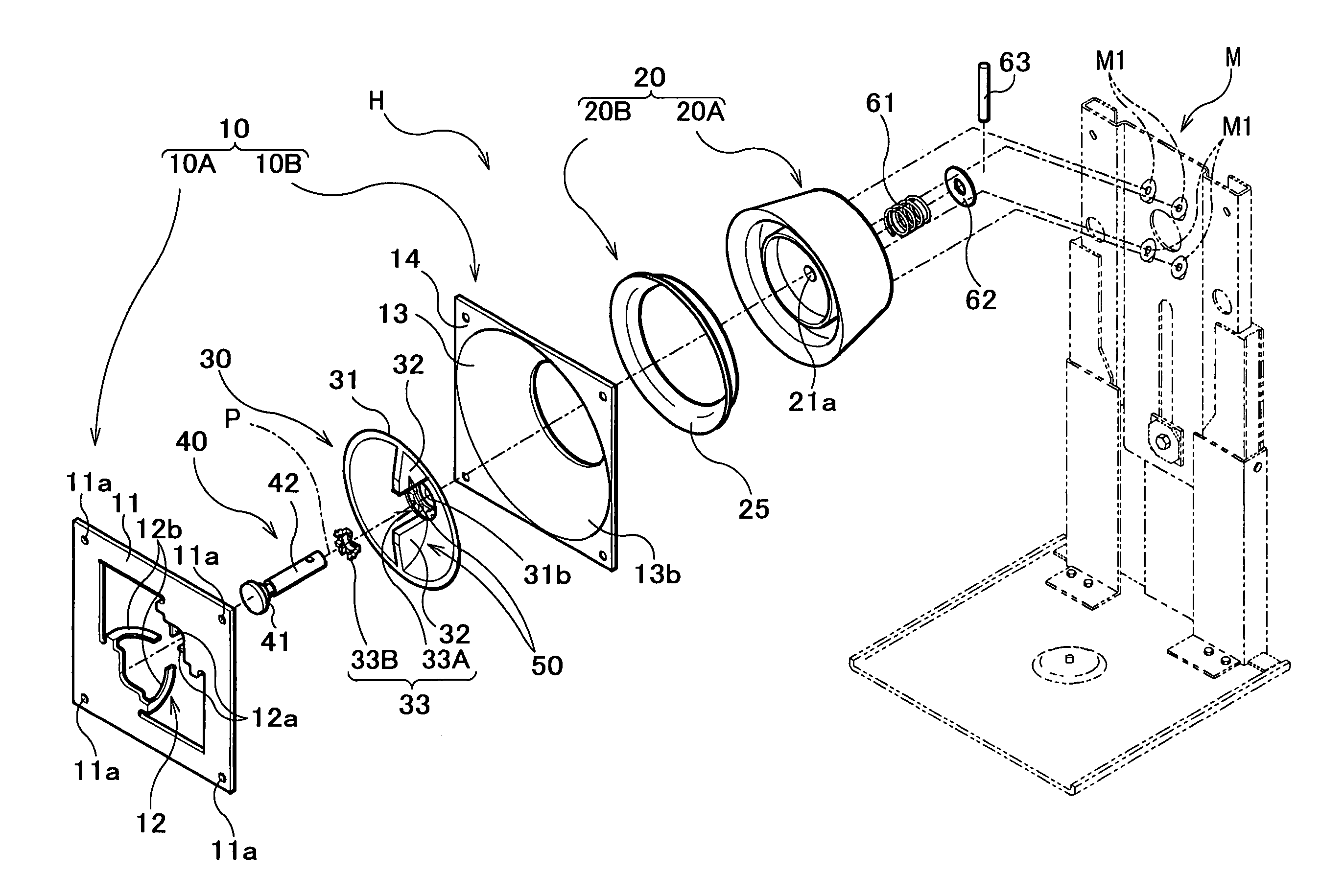
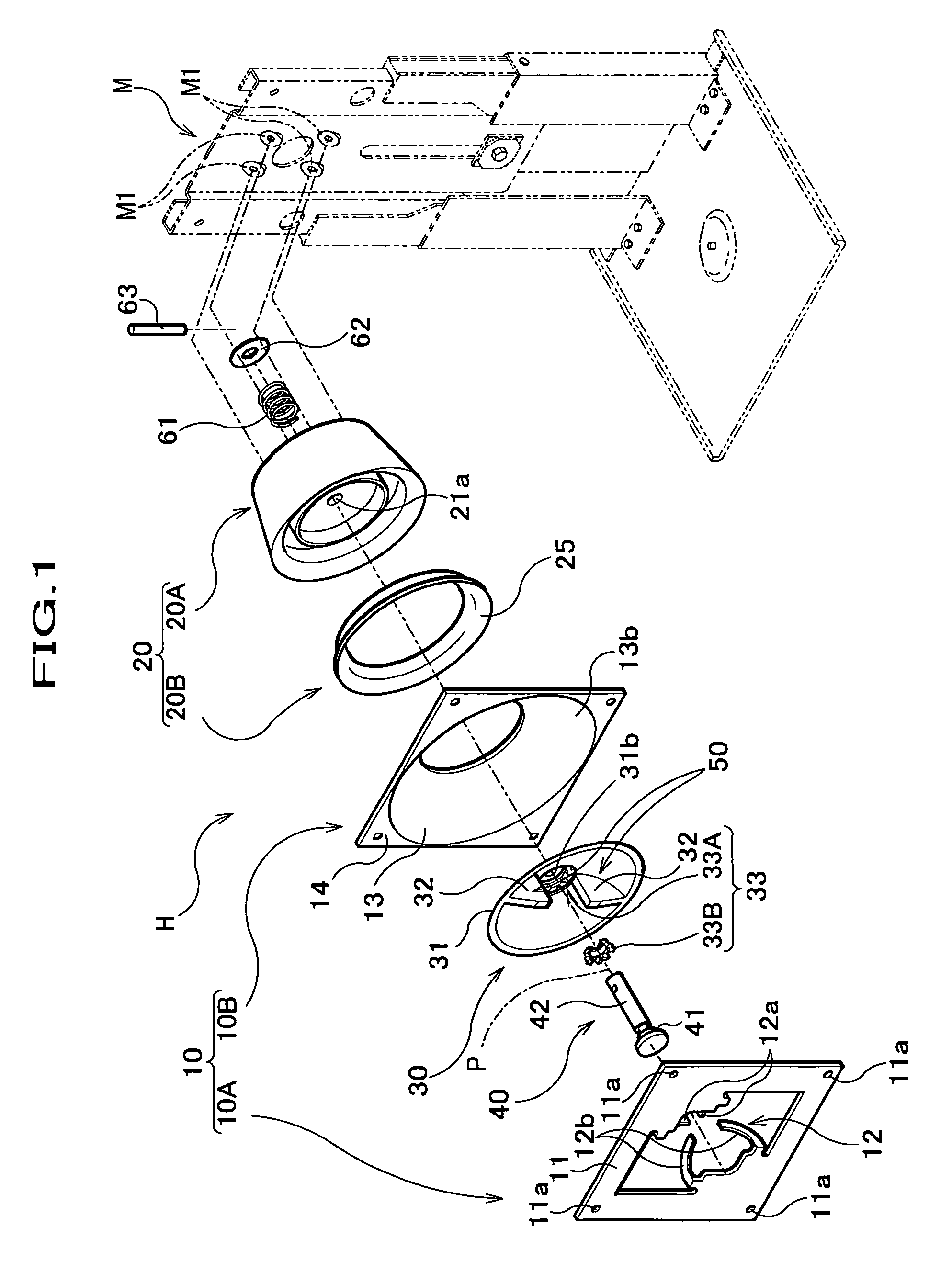
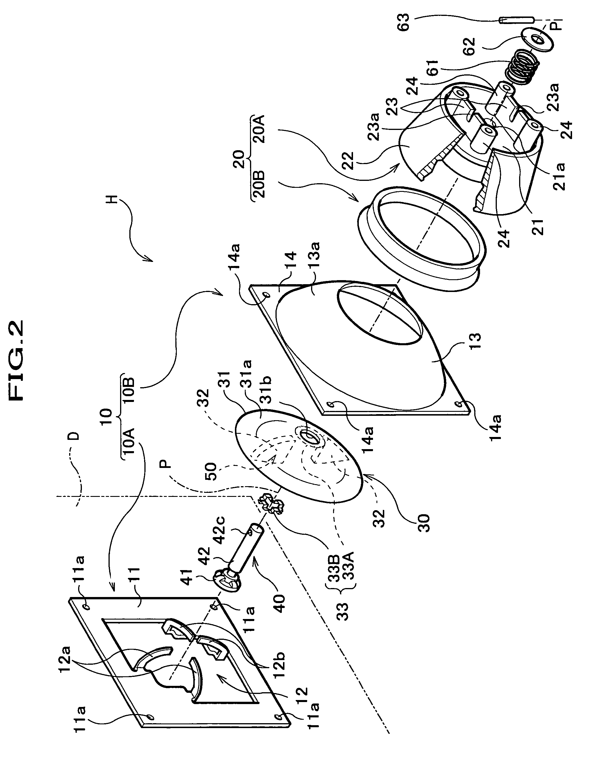
[0055]A first embodiment of the display orientation adjustment apparatus (hereinafter referred to as “orientation adjustment apparatus H”) according to the present invention includes, as shown in FIGS. 1 and 2, a movable part 10 attached to a rear surface of the display D, a base 20 for pivotably supporting the movable part 10, a support cap 30 for pressing the movable part 10 toward a base 20 side, and a corotation restricting member 40 for restricting pivotal motion of the support cap 30. In the support cap 30 is mounted a stopper 50 for restricting a range of pivotal motion of the movable part 10. In this embodiment, the range of pivotal motion of the orientation adjustment apparatus H (i.e., support cap 30 or movable part 10 thereof) within which the display D can be pivoted is set at 90 degrees. This means that the orientation adjustment apparatus H can allow a user to arbitrarily select the orientation (landscape or portrait) of the display D.

[0056]The movabl...

second embodiment

[Second Embodiment]

[0102]A second embodiment of the orientation adjustment apparatus H′ according to the present invention includes, as shown in FIG. 11, a movable part 70 attached to a rear surface of the display D, a base 80 for pivotably supporting the movable part 70, a support cap 90 for pressing the movable part 70 toward a base 80 side, and a corotation restricting member 40 for restricting pivotal motion of the support cap 90. In the support cap 90 is mounted a stopper 95 for restricting a range of pivotal motion of the movable part 70.

[0103]The movable part 70 includes, as shown in FIGS. 11A, 11B, a flat portion 71, a pair of mounting portions 72 disposed parallel to the flat portion 71, and a pair of side plate portions 73 for joining the flat portion 71 to the mounting portions 72.

[0104]The flat portion 71 is provided with an insertion hole 71c substantially in the middle section thereof, and in four places around the insertion hole 71c are projections 71d formed by parti...


PUM


Abstract

A movable part 10 of a display orientation adjustment apparatus H is attached to a rear surface of a display, and pivotably supported by a base 20, and its pivotal motion is restricted by a stopper 50 within a permissible range. If the movable part 10 is pivoted beyond the restricted range by a pivoting force of a predetermined magnitude or greater, the stopper 50 is released. Therefore, even if the display is pivoted inadvertently beyond the permissible range of the pivotal motion, breakage of components thereof would never take place, and its normal state of use can easily be restored.

Description

BACKGROUND OF THE INVENTION[0001]This invention relates to a display orientation adjustment apparatus for pivotably supporting a display of a computer or a television receiver in a manner that permits the display to rotate on (or pivot about) an axis substantially perpendicular to a screen thereof such that pivotal motion of the display takes place in a plane containing the screen.[0002]Historically, computer or television displays (also called “monitors”) have been viewed only in landscape (horizontal) orientation, and thus landscape displays are now in common use. However, in some particular uses, portrait (vertical) orientation may be preferable. For example, in cases where a user uses a computer as a word-processor to edit or view A4 or letter-size documents, portrait viewing orientation fit to the orientation of the documents would serve to save its screen area and to facilitate editing or other word-processing operations.[0003]Against this backdrop, proposed for example in Jap...

Claims


Application Information

Patent Timeline
Patent Type & Authority Patents(United States)
IPC IPC(8): F16M11/12F16M11/02H04N5/64G09F9/00
CPCF16M11/105F16M11/12F16M11/2064F16M11/30F16M2200/041Y10S248/919Y10S248/917
Inventor ISHIZAKI, TAKASHIHIRASAWA, KENICHI
Owner NEC DISPLAY SOLUTIONS LTD
Why Eureka
Try Eureka