
Image Processor, Imaging Apparatus and Image Processing Program

a technology of image processing and image processing program, which is applied in the field of image processing and imaging apparatus, can solve the problems of complex processing steps and high time consumption of each zone for tone transformation processing, and achieve the effect of curtailing the processing time of tone transformation and accurate and rapid implementation

Inactive Publication Date: 2009-02-12
OLYMPUS CORP
View PDF9 Cites 5 Cited by
  • Summary
  • Abstract
  • Description
  • Claims
  • Application Information

AI Technical Summary

Benefits of technology

[0008]According to the invention (1), the image signal is divided into at least one zone or zones, and the image transformation processing by the first transformation means is implemented depending on the zones, so that the tone transformation processing is applied to the image signal obtained by the image transformation processing by the first transformation means. Thus, image processing with the characteristics for each zone in mind is implemented as the pre-processing for the tone transformation processing. In other words, flexible tone transformation processing is applied to the image signal depending on the characteristics of the zones of the divided image signal so that the time taken for tone transformation processing can be curtailed.
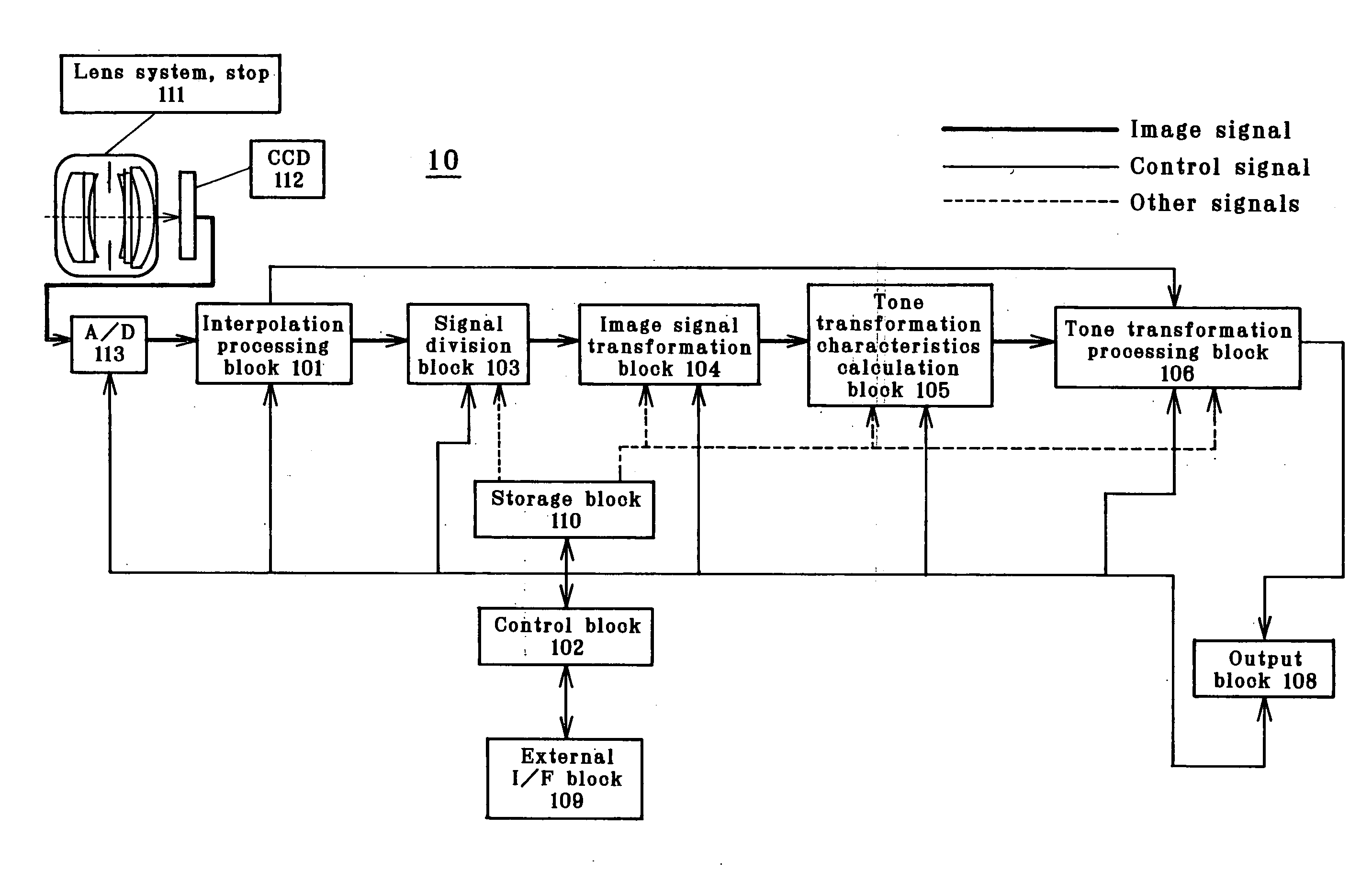
[0011]The invention (3) according to the third aspect is carried out in the first and second embodiments shown in FIGS. 1 to 5. The signal division means is equivalent to the signal division block 103 shown in FIGS. 1 and 3. According to the invention (3), the image signal is divided into at least one zone or zones on the basis of the user's order. According to the invention (3) wherein the image signal is divided into at least one zone or zones using the information designated by the user, there is an increased degree of flexibility in the division of the signal into zones.
[0013]The invention (4) is carried out in the first and second embodiments shown in FIGS. 1 to 5. The processing of decreasing the amount of data is implemented at the image signal transformation block 104 shown in FIGS. 1 and 3. According to the invention (4), the amount of data of the image signal is decreased by image signal transformation processing before the tone transformation characteristics. Thus, by applying tone transformation processing to the image signal with a decreased amount of data, the time taken for tone transformation processing can be curtailed. For instance, if the image signal is divided into at least one zone or zones and the amount of data of the image signal is decreased depending on the degree of importance of the zones, it is then possible to increase the processing speed without detrimental to the image quality of the zone of much more importance.
[0040]In accordance with the invention wherein flexible tone transformation processing is applied to image signals depending on the characteristics of the divided image areas, it is possible to provide an image processor and imaging apparatus capable of curtailing tone transformation processing time as well as an image processing program.

Problems solved by technology

A problem with the method set forth in the aforesaid U.S. Pat. No. 3,465,226 is, however, that the tone transformation processing for each zone takes much time.
A problem with the method set forth in JP(A)2002-94998 is that the processing steps involved are complicated, because tone correction is applied to an images in a frame memory with white balance correction coefficients varying with pixel positions, and gamma tone correction is implemented using individual tone curves depending on the luminance of individual pixel positions.

Method used


Image

  • Image Processor, Imaging Apparatus and Image Processing Program
  • Image Processor, Imaging Apparatus and Image Processing Program
  • Image Processor, Imaging Apparatus and Image Processing Program

Examples


first embodiment

[0050]FIG. 1 is illustrative of the arrangement of the first embodiment comprising the inventive imaging apparatus 10. An image taken via a lens system•stop 111 and a CCD 112 is converted at an A / D 113 into a digital signal. An image signal from the A / D 113 is forwarded to an interpolation processing block 101. The interpolation processing block 101 is connected to a signal division block 103 and a tone transformation processing block 106. The signal division block 103 is connected to an output block 108 via the image signal conversion block 104, a tone transformation characteristics calculation block 105 and a tone transformation processing block 106.

[0051]A storage block 110 is bidirectionally connected to the signal division block 103, image signal conversion block 104, tone transformation characteristics calculation block 105 and tone transformation processing block 106. A control block 102 is bidirectionally connected to the interpolation processing block 101, signal division b...

second embodiment

[0084]FIG. 3 is illustrative of the arrangement of the second embodiment, showing the arrangement that the imaging apparatus 20 has. An image taken via the lens system•stop 111 and CCD 112 is converted at the A / D 113 into a digital signal. An image signal from the A / D 113 is forwarded to the interpolation processing block 101. The interpolation processing block 101 is connected to a tone processing assessment block 200 and the tone transformation processing block 106. The tone processing assessment block 200 is connected to the signal division block 101. The signal division block 103 is connected to the output block 108 via the image signal conversion block 104, tone transformation characteristics calculation block 105 and tone transformation processing block 106.

[0085]The storage block 110 is bidirectionally connected to the tone processing assessment block 200, signal division block 103, image signal conversion block 104, tone transformation characteristics calculation block 105 a...


PUM


Abstract

The invention provides an imaging apparatus wherein an image taken through lens system•stop (111) and CCD (112) are converted by A / D (113) into an image signal which is in turn subjected to tone transformation processing at tone transformation processing (106). The image signal is divided at signal division block (103) into at least one zone or zones, and image transformation processing is applied at image signal conversion block (104) to a digital image signal corresponding to the zone for each zone. Tone transformation characteristics calculation block (105) determines transformation characteristics for tone transformation processing of an image signal generated at image signal conversion block (104). Tone transformation processing block (106) implements tone transformation processing using the transformation characteristics determined at image signal conversion block (104). Such tone transformation processing may be applied to image processors other than the imaging apparatus.

Description

ART FIELD[0001]The present invention relates to an image processor and imaging apparatus capable of curtailing tone transformation processing time, and an image processing program.BACKGROUND ART[0002]In current digital still cameras or video cameras, the tone widths (of the order of for instance 10 to 12 bits) of entered images signals or image signals being processed are set wider than those of final output signals (for instance 8 bits) for the purpose of preventing an image quality deterioration by reason of shifts in digital signal processing. In that case, tone transformation must be implemented in such a way as to match with the tone width in the output system. So far, this has been implemented with fixed tone characteristics for a standard scene. Further, there has also been an adaptive transformation method proposed, which involves dividing an image signal into multiple zones, and applying tone transformation to the image signal with tone transformation characteristics varied...

Claims


Application Information

Patent Timeline
Patent Type & Authority Applications(United States)
IPC IPC(8): G06K9/36H04N23/76
CPCG06T5/009G06T5/40G06T2207/20021H04N9/69H04N5/20H04N5/23245H04N1/407H04N23/667G06T5/92H04N23/83
Inventor ON, SEIGO
Owner OLYMPUS CORP
Learn More