Battery with strength indicator

a technology of strength indicator and battery, which is applied in the field of battery with strength indicator, can solve the problems of not telling the purchaser the actual condition of the battery, the capacity cannot be determined by taking specific gravity measurements, and the voltmeter is expensive, so as to reduce the cross sectional area, the effect of quick indication to the user of the strength of the battery and sufficient heat generation capacity

Inactive Publication Date: 2005-12-20
STRATEGIC ELECTRONICS
View PDF133 Cites 21 Cited by
  • Summary
  • Abstract
  • Description
  • Claims
  • Application Information

AI Technical Summary

Benefits of technology

[0011]In a preferred embodiment shown further herein, the improved battery having a battery strength indicator comprises a dry cell battery having a first terminal and a second terminal; a battery indicator formed in a layer attached to a side of the battery which undergoes a visible change when subject to a predetermined voltage potential and a first conductor electrically connected between one end of the indicator and the first battery terminal; and a battery switch comprising a resilient, nonconductive, deformable layer disposed over the side of the battery, a switch chamber formed beneath the resilient layer, and a second conductor extending from the chamber and connected to the other end of the indicator, the portion of the second conductive lead within the switch chamber comprising a switch contact, the battery switch being biased in an electrically open position. Upon pressing of the resilient layer over the switch chamber, the switch contact will be placed in electrical contact with a conductive layer in electrical contact with the second battery terminal, thereby placing the indicator in electrical contact across the terminals of the battery to quickly indicate to the user the strength of the battery.
[0012]In another preferred embodiment shown herein, the improved battery having a battery strength indicator comprises a dry cell battery having a first terminal and a second terminal; a battery indicator attached to a side of the battery which undergoes a visible change when subject to a voltage potential which exceeds or drops below a predetermined value and a first conductor electrically connected between one end of the indicator and the first battery terminal; and a battery switch comprising a resilient, nonconductive, deformable layer disposed over the side of the battery, a switch chamber formed beneath the resilient layer, a second conductor extending from one end of the chamber and connected to the other end of the indicator, and a third conductor extending from the other end of the chamber to the second battery terminal, the battery switch being biased in an electrically open position. Upon pressing of the resilient layer over the switch chamber, the switch places the indicator in electrical contact across the terminals of the battery to quickly indicate to the user the strength of the battery.
[0013]In yet another embodiment, the invention is directed to a strip or label for application to a battery which includes an integral battery-strength indicator or voltmeter which comprises a first nonconductive insulating or dielectric base layer and a conductive layer above and in contact with the base layer. A nonconductive insulating or dielectric layer may be provided over and in contact with the conductive layer. A heat or temperature sensitive, color indicating layer thermally contacts the conductive layer. The conductive layer has sufficient heat generating capacity when subject to a predetermined voltage to cause a color change in the temperature sensitive, color indicating layer. The conductive layer is preferably formed with a reduced cross sectional area to have a resistance such that current flow at a minimum predetermined voltage through the conductive layer will raise the area to a predetermined temperature. The base layer is of sufficient thickness to provide thermal insulation to overcome heat sinking under the conductive layer and permit the temperature sensitive, color indicating layer to function when the strip containing the battery strength indicator or voltmeter is applied to the side or housing of a battery, which battery typically has an electrically conductive housing. The strip comprising the battery-strength indicator or voltmeter also includes switch means adapted to make electrical contact with a terminal of the battery, which terminal may comprise the electrically conductive battery housing.

Problems solved by technology

A dry-cell battery does not have a reservoir liquid electrolyte; thus, its capacity cannot be determined by taking specific gravity measurements.
In addition, voltmeters are expensive, as are devices for measuring the voltage output of a battery, both under a load and under no load.
Although this date-stamping may be of some benefit to purchasers, it does not tell the purchaser the actual condition of the battery.
Moreover, date-stamping of the package does not include date-stamping of the battery; thus, the purchaser has no idea of the use-date of a particular battery once it has been removed from the package.
Although it is not complicated to test batteries, it is time consuming to disassemble a device, remove the batteries, test the batteries, and, if they pass the test, reinstall the batteries in the device.
It is normally not possible to test new batteries at the time of purchase because of the battery protective packaging.

Method used


Image

  • Battery with strength indicator
  • Battery with strength indicator
  • Battery with strength indicator

Examples


Embodiment Construction

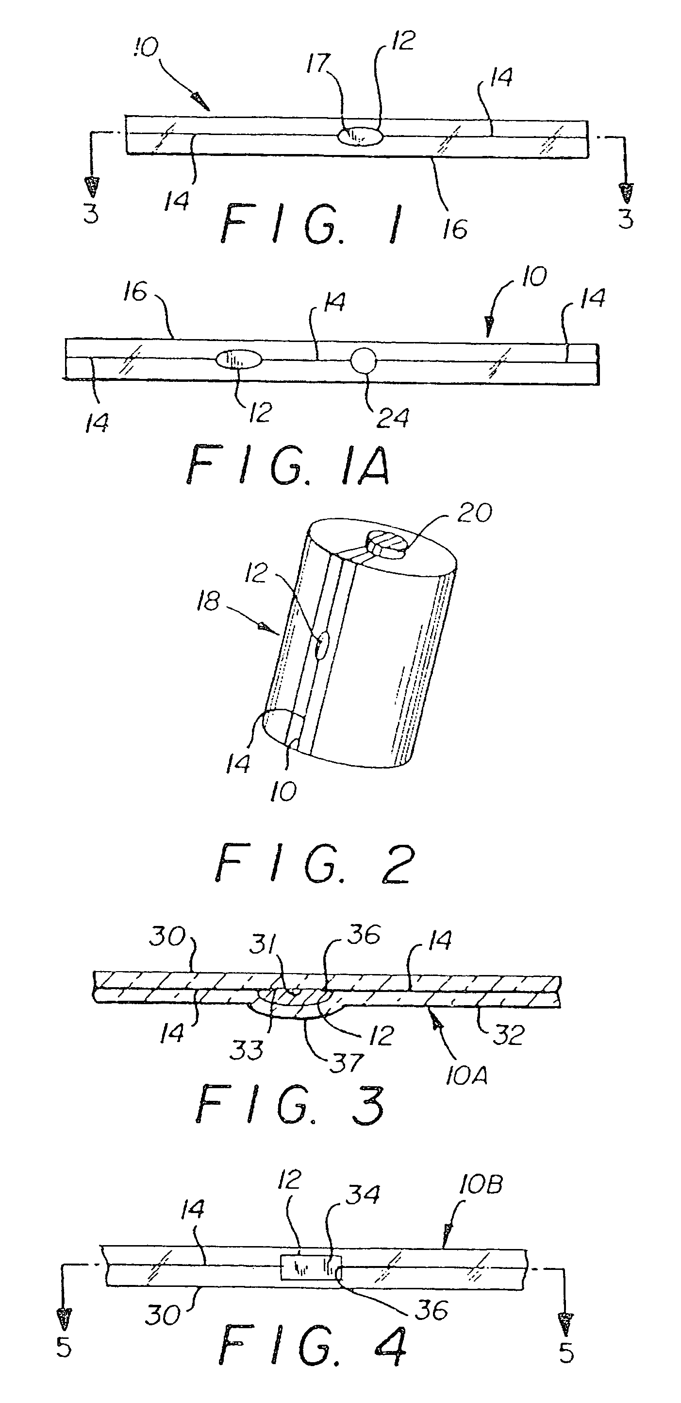
[0040]Referring to FIG. 1, a battery-strength indicator device 10 of the present invention is illustrated. The indicator device has an indicator chamber, cell or bubble 12 formed in strip 16. Preferably the cells of the present invention are sealed cells. Conductive layers 14 run the length of the strip into the indicator bubble to form spaced apart electrodes. The indicator bubble contains an indicating material 17 which undergoes a visible change when the voltage potential across the indicator cell exceeds a predetermined value. At least one side of the strip 16 is transparent or translucent.

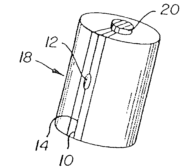
[0041]The improved battery 18 of the present invention is illustrated in FIG. 2. The battery has an anode 20 and a cathode at its base (not shown). The indicator device 10 is attached to the side of the battery, with the ends of the device connected to the anode 20 and the cathode. If the device is a constant-drain device, that is, the device is on continuously, the indicator cell undergoes a ...


PUM

PropertyMeasurementUnit
depthaaaaaaaaaa
depthaaaaaaaaaa
heightaaaaaaaaaa

Abstract

A battery strength indicating and switch means on a battery which is coupled across the terminals of the battery and which is provided with an indicating means to indicate the strength of the battery and in addition, the battery strength indicating means is also provided with an in-line switch which can easily be depressed to complete the circuit so as to place the indicator means across the terminals of the cell and display the charge of the battery.

Description

[0001]This is a continuation Ser. No. 07 / 816,144 filed on Dec. 31, 1991, now U.S. Pat. No. 5,156,931.FIELD OF THE INVENTION[0002]The present invention relates to an improved battery having a built-in strength indicator device for determining the strength, voltage, or capacity of the battery. More particularly, the present invention relates to a battery having an indicator cell which visually indicates when the battery is above or below a predetermined voltage value, an LED array which indicates when the battery is above or below a predetermined voltage value, or a redox cell which indicates when the voltage output is above or below a predetermined voltage by a color change.BACKGROUND OF THE INVENTION[0003]Batteries are employed extensively in this country and abroad for automobiles, home uses, industrial uses, recreational uses, and military uses. A battery is normally tested by measuring its voltage output without a load. If the voltage is below a predetermined value, and the volta...

Claims


Application Information

Patent Timeline
Patent Type & Authority Patents(United States)
IPC IPC(8): A47C3/34G01R31/36H01M2/10H01M6/50
CPCA47C3/34G01R31/3682H01M2/105H01M6/5044G01R31/3646H01M50/213
Inventor BURROUGHS, JAMES R.O'KAIN, ALAN N.
Owner STRATEGIC ELECTRONICS
Why Eureka
Try Eureka