Pit road display

a technology for pit roads and gauges, applied in the direction of instruments, transportation and packaging, instrument arrangements, etc., can solve the problems of driver division of attention, driver risking losing position in a race, and lapse in attention can have catastrophic consequences

Inactive Publication Date: 2009-10-22
SULLIVAN JOHN T +1
View PDF0 Cites 7 Cited by
  • Summary
  • Abstract
  • Description
  • Claims
  • Application Information

AI Technical Summary

Benefits of technology

[0023]It is accordingly a first objective of the present invention to provide an instrument or gauge for a vehicle that provides critical information to a driver through peripheral vision, so to minimize the need for the driver to turn attention away from the raceway track, or road.
[0024]It is a second objective of the invention to provide an instrument or gauge for a vehicle that provides a rapid indication of sensor loss with a minimum of false indications.

Problems solved by technology

The nature of NASCAR racing, and in particular the high speeds and close proximity at which the vehicles are driven, requires the driver to devote maximum attention to the track and other vehicles, since any lapse in attention can have catastrophic consequences.
This results in the problem that the driver must divide attention between the roadway and the tachometer.
Conventional tachometer displays are extremely difficult to follow solely through peripheral vision, and since the penalties for exceeding the pit road speed limit for a particular track are severe, drivers tend to drive at an engine speed that is lower than optimal, causing the driver to risk loss of position in a race by prolonging the time spent off the track in the pit area.
If the driver attempts to keep the engine speed closer to the pit road limit by spending more time observing the tachometer, the driver risks running into a vehicle entering pit road from one of the pit areas.
These problems are compounded by differences in the permitted speed for different tracks, which depend on the configuration of the pit road and local conditions, and also because the relationship between vehicle and engine speed can vary, necessitating that a certain “fudge” factor be built into the engine speed calculations, making it even more difficult for the driver to control engine speed by “feel” rather than by observing the tachometer.
During a race, safety hazards, such as damage to a vehicle caused by flying debris, can arise very suddenly and require an extremely short reaction time on the part of the driver.
However, the visual distractions and noise that occurs during normal racing are such that the driver may not notice the conventional warning in time to take action.
Furthermore, problems that have about to become critical may only be indicated by the conventional analog display, which is difficult to read without in fine enough detail to indicate the developing hazard.
However, if the delay time is too great, the driver may not be given adequate notice of the loss of a sensor, while if the delay time is too short, false alarms may still occur.
However, since the tachometer and manifold absolute pressure (MAP) inputs to the conventional boost controller do not provide a clear indication as to what gear the vehicle is in, automated traction control adapters are conventionally complicated and expensive.
This problem results from the fact that different sensors have different outputs.
As a result, a typical fuel gauge can only be used with a specific type of fuel sensor.

Method used


Image

  • Pit road display
  • Pit road display
  • Pit road display

Examples


Embodiment Construction

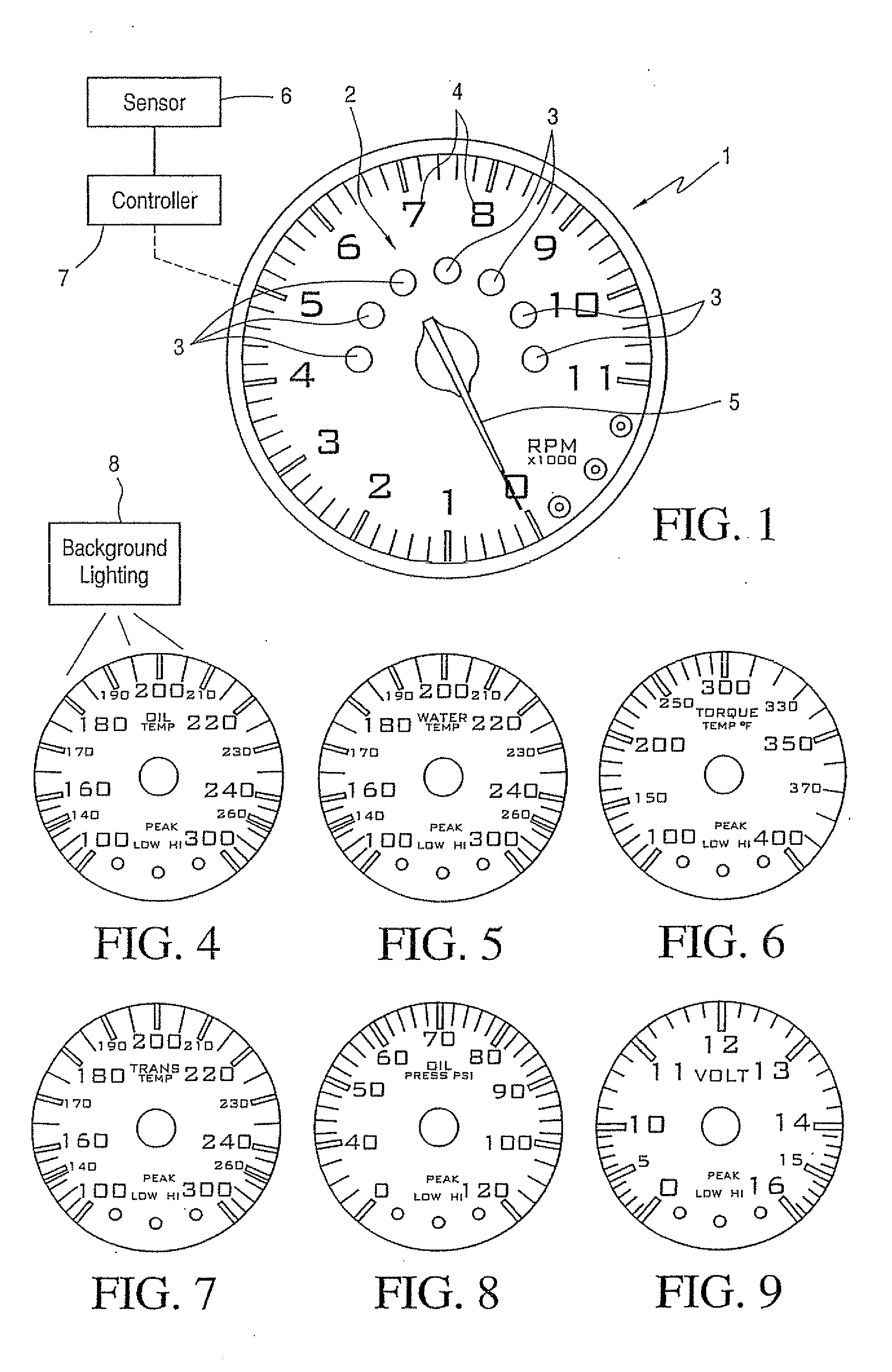
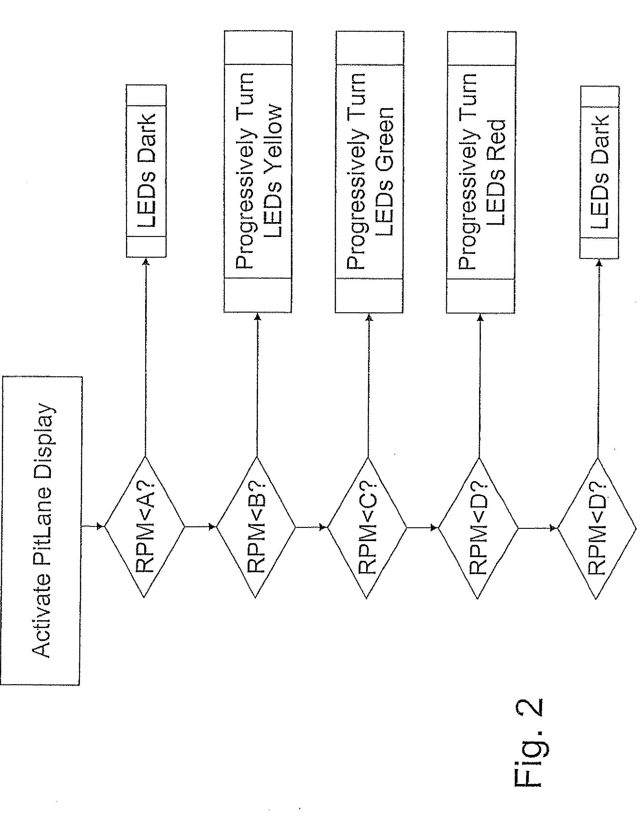
[0044]FIG. 1 shows a tachometer 1 having a secondary display 2 that includes seven indicator lights 3 arranged to be successively illuminated in order to indicate shift points. The seven indicator lights 3 are preferably in the form of multi-color LEDs having a brightness sufficient to enable the lights to be seen using the driver's peripheral vision. The lights 3 may be progressively illuminated such that the leftmost light will be illuminated first, followed by the leftmost light and the adjacent light, followed by the leftmost three lights, and so forth until all seven lights are illuminated. This pattern of progressive illumination may be referred to as a progressive illumination sequence. Preferably, three such progressive illumination sequences are provided, including a first in which the lights being illustrated are all green, a second in which the lights being illuminated are all yellow, and a third in which the lights being illuminated are all red,

[0045]The tachometer also ...


PUM


Abstract

Instruments or gauges arranged to provide feedback detectable by the peripheral vision of a driver when vehicle operating parameters, such as engine speed, temperature, pressure, and voltage, are in a critical range, include one or more of the following types of instruments or gauges and / or features: (a) a tachometer that not only includes a primary numeric display, but also a secondary display made up of a plurality of discrete lights of different colors, the colors indicating whether the engine speed of a vehicle is within a relatively narrow range of engine speeds acceptable for the roadway leading from a race track to service areas, known as “pit road,” the high and low limits of the range being adjustable to meet pit road requirements at different tracks; (b) an instrument or gauge having a background that illuminates to indicate critical sensor readings; (c) an instrument or gauge having improved handling of sensor abnormalities to prevent false readings; (d) a non-linear analog gauge for a motor vehicle having a higher resolution in a particular range of interest, and a lower resolution outside that range; and (e) a boost pressure gauge that facilitates entry of gear information for use in traction control. The instruments or gauges of the invention are suitable for use in racing vehicles that meet standards established by NASCAR.

Description

[0001]This application claims the benefit of provisional U.S. Patent Application Ser. No. 61 / 064,662, filed Mar. 19, 2008.BACKGROUND OF THE INVENTION[0002]1. Field of the Invention[0003]This invention relates to instruments or gauges for Ls in vehicles, and in particular to instruments or gauges that provide feedback detectable by the peripheral vision of a driver when vehicle operating parameters, such as engine speed, temperature, pressure, and voltage, are in a critical range. The instruments or gauges of the invention are especially suitable for use in racing vehicles that meet standards of the National Association for Stock Car Auto Racing (NASCAR), although they may also be used in other types of racing and non-racing vehicles.[0004]The instruments or gauges of the invention may include one or more of the following types of instruments or gauges and / or features:[0005]a. A tachometer that not only includes a primary numeric display, but also a secondary display made up of a plu...

Claims


Application Information

Patent Timeline
Patent Type & Authority Applications(United States)
IPC IPC(8): B60Q1/00
CPCB60Q9/00B60K37/02G01D11/28G01D3/08
Inventor SULLIVAN, JOHN T.PARKS, STEVE
Owner SULLIVAN JOHN T
Why Eureka
Try Eureka