Method of Carrying Out Land Based Projects Using Aerial Imagery Programs

a technology of aerial imagery and land based projects, applied in image analysis, image enhancement, texturing/coloring, etc., can solve the problem that there is no other calculation capability of such programs, and the thought of providing i

Inactive Publication Date: 2016-09-01
NIEMCZYK ANDREW
View PDF2 Cites 8 Cited by
  • Summary
  • Abstract
  • Description
  • Claims
  • Application Information

AI Technical Summary

Benefits of technology

[0014]The above recited object and other objects which will be appreciated by those skilled in the art are achieved by adding certain capabilities to Google Earth and other similar land aerial imaging programs which will assist a user in planning a project. One capability is to be able to create display of a line of markers on the program image of an area with the earth's surface at any user selected spacing along a line delineating a selected subregion of interest or elsewhere within a selected subregion so as to quickly indicate to the user the total number of components corresponding to the markers such as fence posts. The program also can have the capability of totaling up the number of markers (and fence posts) spaced along the line. The markers could correspond to other elements such as drilled hole patterns and pumps for the project described above.
[0015]Another added capability of the present invention is the ability to calculate the user of any subregion delineated by the use in selected measurement units as for carrying out a paving project, and the total volume of material for a paving area of a user selected thickness in the case of continuous paving. This enables a user to quickly determine the total volume of materials such as poured concrete, asphalt or the like needed to carry out the project. Also, the number of paving bricks or stones for a non continuous pavement needed for paving a delineated subregion may be calculated.
[0017]Thus, the usefulness of aerial image programs can be greatly enhanced for the benefit of contractors, homeowners or others since these added capabilities may eliminate the need for making measurements in the field and for preparing layout drawings.

Problems solved by technology

While the total length of a boundary line can be generated by existing programs, no other calculation capability of such programs is thought to have heretofore been provided, such as to aid in calculations completing out such projects.

Method used


Image

  • Method of Carrying Out Land Based Projects Using Aerial Imagery Programs
  • Method of Carrying Out Land Based Projects Using Aerial Imagery Programs
  • Method of Carrying Out Land Based Projects Using Aerial Imagery Programs

Examples


Embodiment Construction

[0027]In the following detailed description, certain specific terminology will be employed for the sake of clarity and a particular embodiment described in accordance with the requirements of 35 USC 112, but it is to be understood that the same is not intended to be limiting and should not be so construed inasmuch as the invention is capable of taking many forms and variations within the scope of the appended claims.

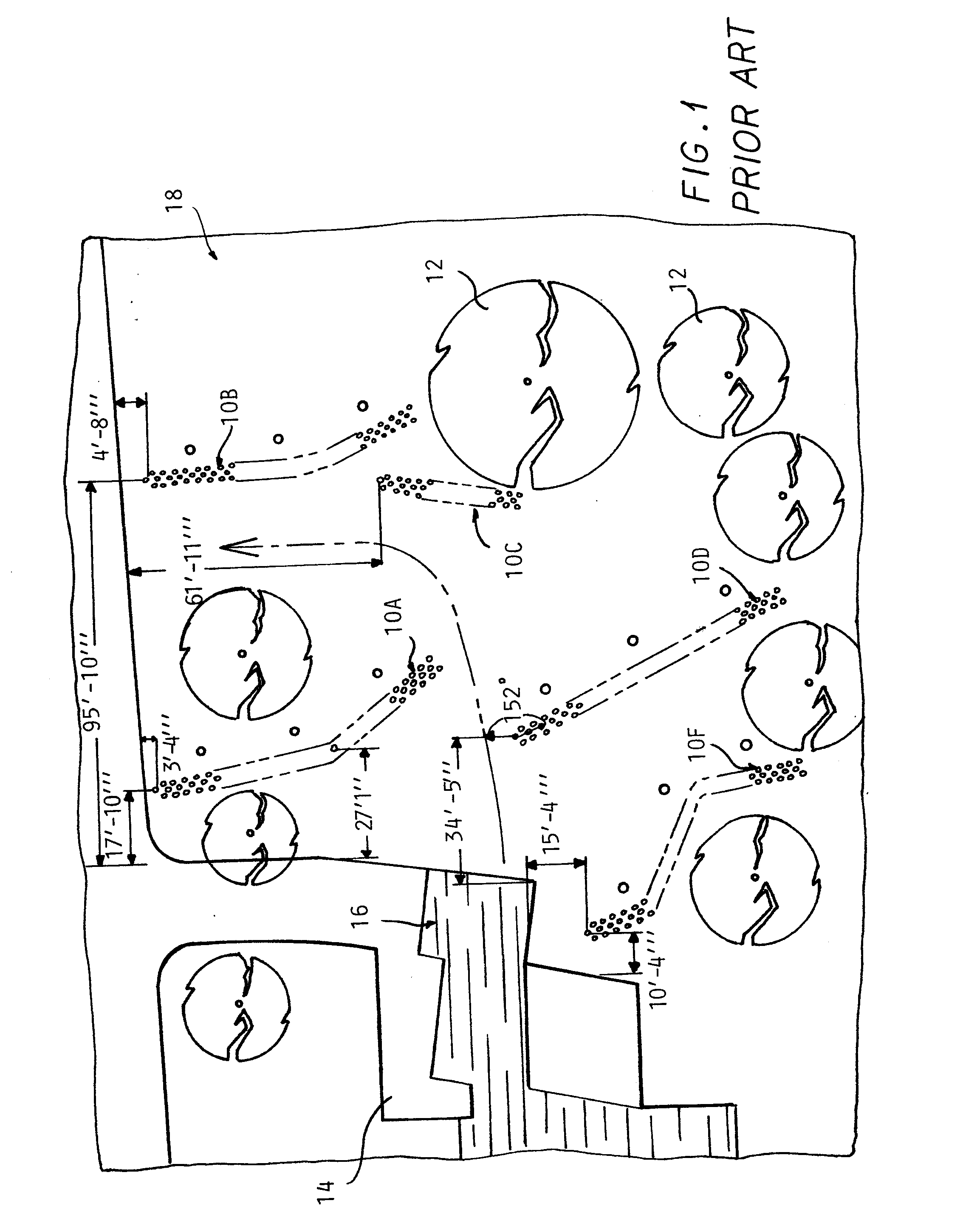
[0028]Referring to FIG. 1, a partial layout drawing 18 is depicted, prepared by conventional drafting techniques. Such features as trees12, pavement areas 14, and buildings 16 are shown. Such a drawing is associated with the installation of several arrays 10A-10F of tubular passive pumps represented by the small circles drawn therein inserted in holes first drilled into the ground, as described in U.S. Pat. No. 8,562,250 issued to the present inventor.

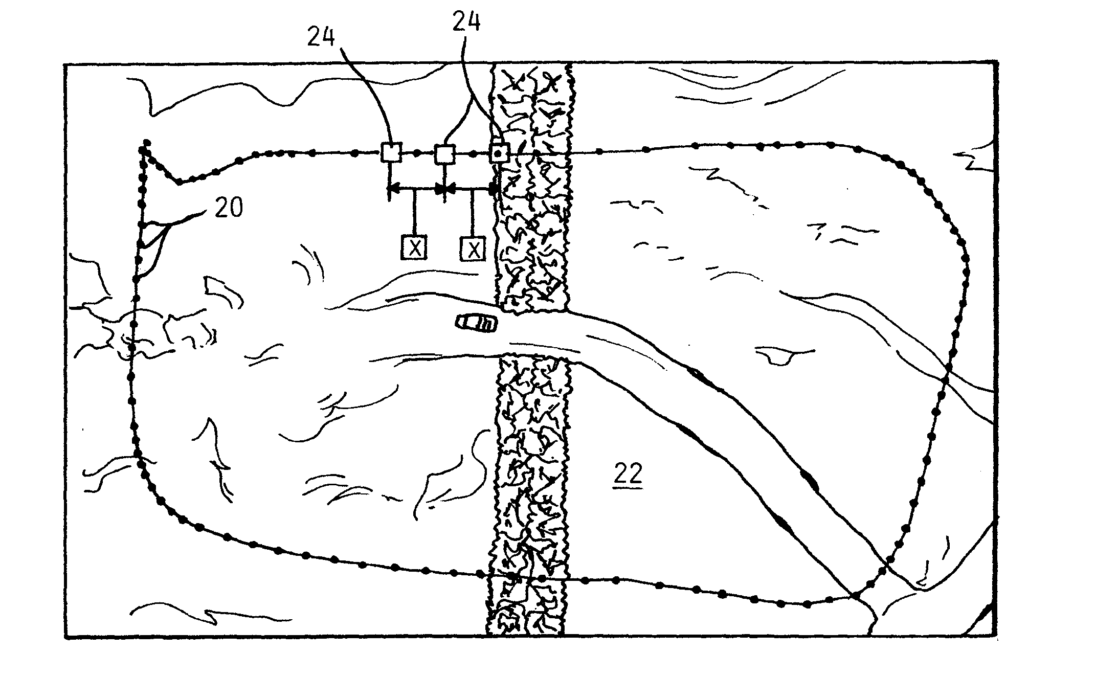
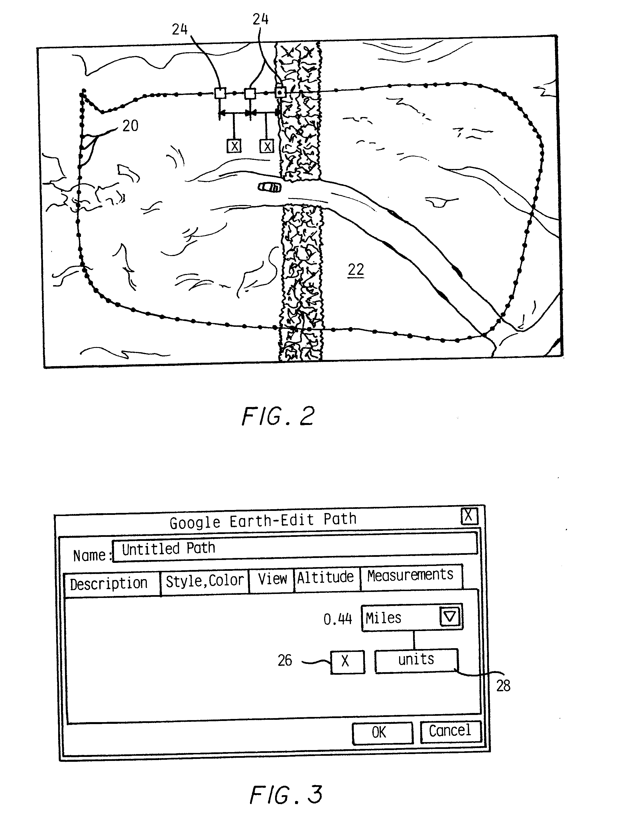
[0029]The location and configuration of those arrays is determined by a hydrological analysis and must be laid out prior ...


PUM


Abstract

Additional capabilities added to an aerial image programs are disclosed including enabling the user to generate a series of markers to an aerial image at a user selected spacing, and to enable calculations of an aerial image and allow the user to enter data to be used in these calculations, for facilitating projects such as paving, decking, roofing and fertilizing in user delineated subregions of an aerial image.

Description

CROSS REFERENCE TO RELATED APPLCATIONS[0001]This application claims the benefit of U.S. provisional application no. 61 / 945,310 filed on Feb. 27, 2014.BACKGROUND OF THE INVENTION[0002]This application concerns facilitating planning of various projects carried out on land areas, such as paving, roofing, building decks and fertilizing.[0003]Such projects often involve laying out the project on a drawing so as to determine the material requirements of the project, such as the quantity of material needed the number of components, etc.[0004]Common examples are projects for paving particular areas, which require that the quantity of paving material must to be determined, or for building a fence in which the number of posts must be determined.[0005]The present inventor has developed a way to enhance the percolation of surface water into the ground, involving drilling a series of hole patterns into the ground along a path and installing tubular passive pumps into the drilled holes.[0006]See ...

Claims


Application Information

Patent Timeline
Patent Type & Authority Applications(United States)
IPC IPC(8): G06T7/00G06T11/60G06T15/08
CPCG06T7/0081G06T15/08G06T2207/30188G06T2207/10032G06T2207/30184G06T11/60G06T2207/20104G06T7/62G06F3/0482G06F3/04845G06T11/001G06T2200/24
Inventor NIEMCZYK, ANDREW
Owner NIEMCZYK ANDREW
Why Eureka
Try Eureka