Anode utilization control system for a fuel cell power plant

a fuel cell power plant and utilization control technology, applied in the direction of emergency supply, electrical generators, sustainable buildings, etc., can solve the problems of insufficient basic control, insufficient basic control, and insufficient basic control, so as to reduce or eliminate the need for time-consuming and expensive factory-tuning, and facilitate access. , the effect of rapid indication of changes in anode utilization

Inactive Publication Date: 2011-09-08
HYAXIOM INC
View PDF6 Cites 7 Cited by
  • Summary
  • Abstract
  • Description
  • Claims
  • Application Information

AI Technical Summary

Benefits of technology

[0020]Use of the present oxygen sensor and oxygen sensor controller to control anode utilization provides many benefits. First, the oxygen sensor may be placed at a location adjacent the burner exhaust that is much easier to access for purposes of efficiency of installation, maintenance and replacement of the sensor without significant disruption to the operation of the power plant. Second, the oxygen sensor provides rapid indications of changes in anode utilization without a need to await for subsequent changes in temperatures within the reformer. Additionally, use of the present oxygen sensor and oxygen sensor controller to control anode utilization reduces or eliminates any need for time-consuming and expensive factory-tuning of a schedule for reformer temperature set point as function of fuel cell current.
[0021]Perhaps most importantly, experimentation with the present anode utilization control system demonstrates that adjusting flow of fuel feedstock into the reformer to maintain a constant burner exhaust oxygen concentration while holding electrical current produced by the power plant fixed and while holding burner air fixed, effectively maintains anode utilization within a optimal utilization band, and thereby eliminates any transient impact resulting from disturbances in fuel heating value of the fuel feedstock, hydrogen production efficiency the fuel processing system, and / or a changes in a steam carbon ratio within the fuel processing system.

Problems solved by technology

For fuel cell power plants that are configured to operate as long-term stationary power plants, efficient control of a rate of flow of the fuel feedstock into the fuel processing system and the resultant flow of hydrogen into the fuel cells of the plant requires precise management as a result of unpredictable disturbances that affect such power plants.
A fundamental disturbance affecting load-following fuel cell power plants is a change in power demand.
This basic control mechanism is necessary, but not sufficient, to adequately control the flow of hydrogen-rich reformate fuel to fuel cell anodes.
The basic control is not adequate because there are other disturbances that affect the power plant, even when power demand is constant.
One such disturbance is the fluctuating fuel heating value of a fuel such as natural gas.
A second common disturbance includes changes in fuel processing system hydrogen conversion efficiency.
As an example, in a catalytic steam reformer, it is known that the effectiveness of the catalysts deteriorates over any given reformer life span.
A third disturbance giving rise to current transients is changes in a steam-carbon ratio within the reformer.
For most fuel cells it is known that having the anode utilization exceed the optimal range gives rise to damage to the anode catalyst and / or support materials for the catalyst.
In contrast, operating the fuel cell at an anode utilization below the optimal range causes loss of valuable hydrogen fuel.
While the reformer temperature control system provides acceptable operation of the fuel cell power plant, the system involves great costs and requires enormous care.
If such a temperature sensor malfunctions, it is extremely costly and disruptive to operation of the power plant to remove and replace the broken sensor within the complex reformer of the fuel processing system.
Moreover, such sensors are necessarily very expensive.

Method used


Image

  • Anode utilization control system for a fuel cell power plant
  • Anode utilization control system for a fuel cell power plant

Examples


Embodiment Construction

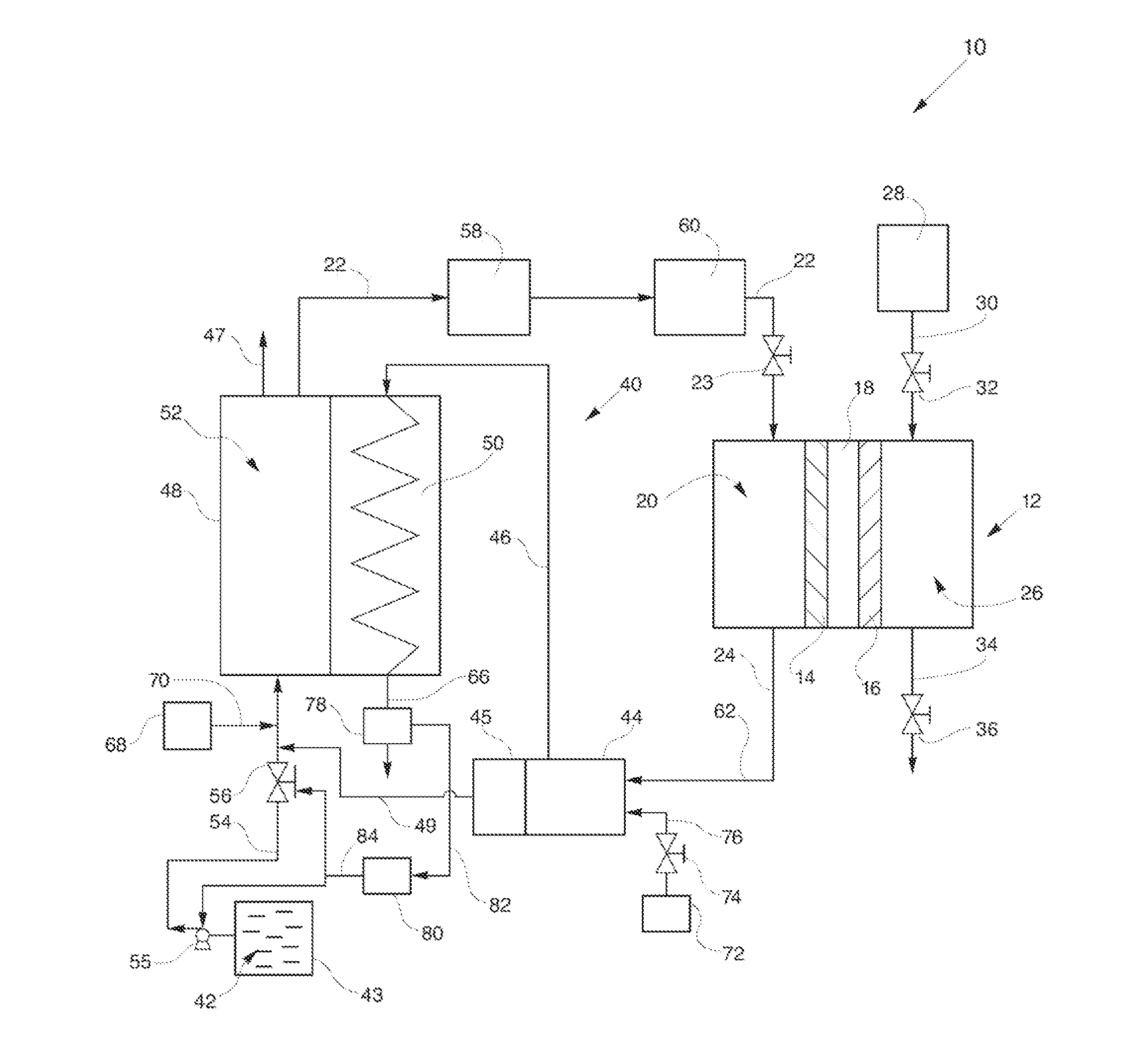
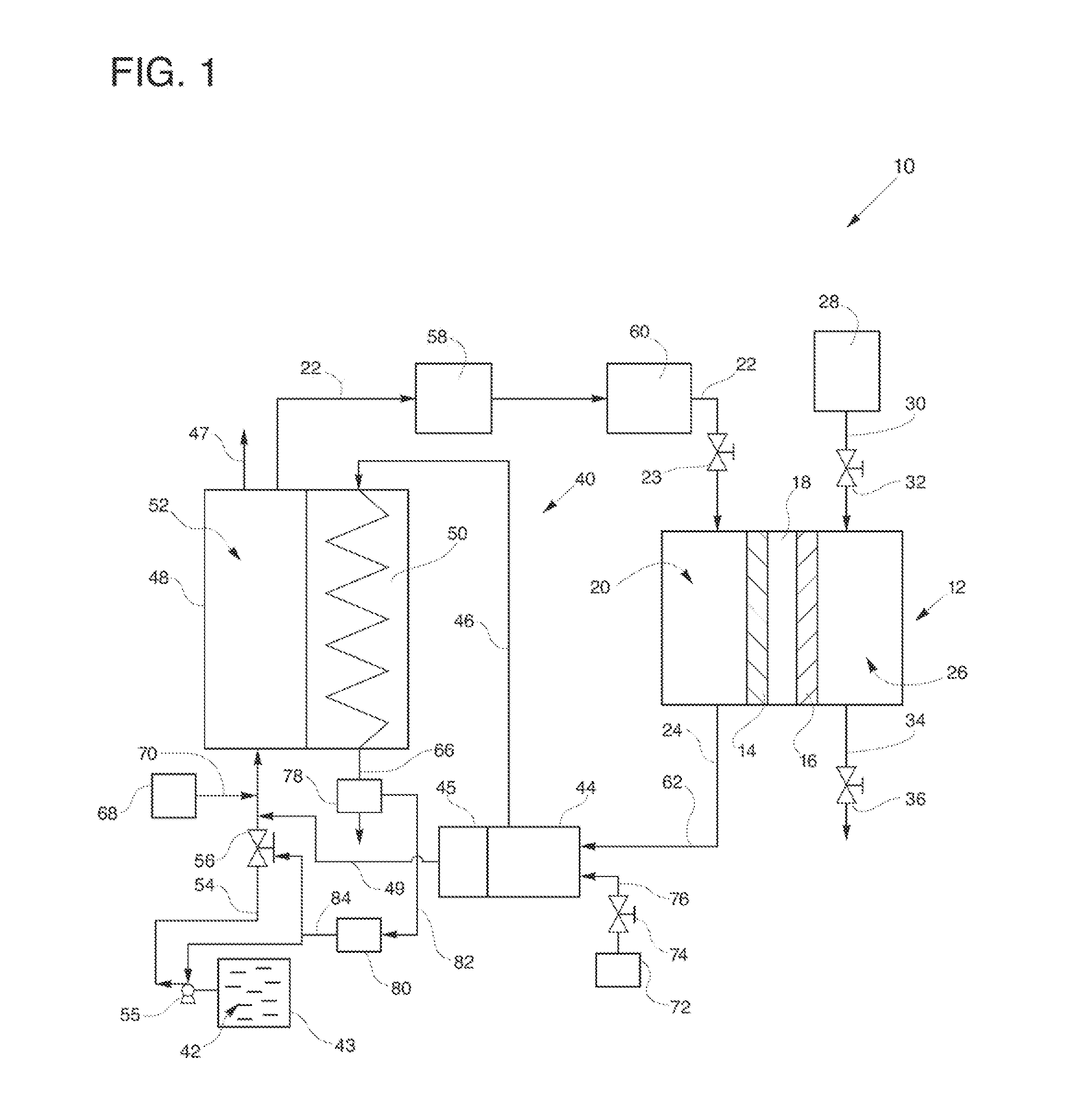
[0026]Referring to the drawings in detail, an anode utilization system for a fuel cell power plant is shown in FIG. 1 and is generally designated by the reference numeral 10. The system or power plant 10 includes at least one fuel cell 12 including an anode catalyst 14 and a cathode catalyst 16 secured to opposed sides of an electrolyte 18, an anode flow field 20 defined in fluid communication with the anode catalyst 14 and with a fuel inlet line 22 for directing flow of a hydrogen-rich fuel stream from the fuel inlet line 22 and through the anode flow field 20, adjacent the anode catalyst 14 and out of the anode flow field 20 through an anode exhaust 24 and anode exhaust valve 25. The fuel inlet line 22 includes a fuel inlet valve 23 for selectively controlling flow of the fuel into the anode flow field 20.

[0027]The fuel cell 12 also includes a cathode flow field 26 defined in fluid communication with the cathode catalyst 16 and with an oxidant source 28 for directing flow of an ox...


PUM

PropertyMeasurementUnit
temperaturesaaaaaaaaaa
electrical currentaaaaaaaaaa
heataaaaaaaaaa

Abstract

The control system (10) utilizes an oxygen sensor (78) to sense an oxygen concentration within a burner exhaust (66) of a fuel processing system (40), wherein the burner device (44) utilizes an anode exhaust stream from a fuel cell (12) to supply heat to a reformer (48). If the anode utilization by the fuel cell (12) anode (14) exceeds an acceptable range, less hydrogen is available for the burner device (44) and more oxygen will therefore be sensed by the oxygen sensor. An oxygen sensor controller (80), in response to the increase in sensed oxygen, increases flow of a fuel feedstock (42) into the reformer (48) to provide more hydrogen fuel to the anode (14) to thereby return anode utilization to an acceptable anode utilization range. An opposite control sequence occurs if anode utilization falls below the acceptable range.

Description

TECHNICAL FIELD[0001]The present disclosure relates to fuel cell power plants that are suited for usage in transportation vehicles, portable power plants, or as stationary power plants, and the disclosure especially relates to a system and method for controlling use of a hydrogen-rich fuel at an anode of a fuel cell power plant that utilizes fuel produced by a reformer within a fuel processing system of the plant.BACKGROUND ART[0002]Fuel cells are well known and are commonly used to produce electrical current from a hydrogen-rich fuel stream and an oxygen-containing oxidant stream to power electrical apparatus. Fuel cells are typically arranged in a cell stack assembly having a plurality of fuel cells arranged with common manifolds and other components such as a fuel processing system, controllers and valves, etc. to form a fuel cell power plant. In such a fuel cell power plant of the prior art, it is well known that fuel is produced by the fuel processing system reformer and the re...

Claims


Application Information

Patent Timeline
Patent Type & Authority Applications(United States)
IPC IPC(8): H01M8/06
CPCH01M8/04022H01M8/04089H01M8/0618H01M8/0662H01M8/086Y02T90/32H01M2250/10H01M2250/20Y02E60/50Y02B90/14H01M2008/1095Y02B90/10Y02T90/40H01M8/04H01M8/06H01M8/10
Inventor ISOM, JOSHUA
Owner HYAXIOM INC
Why Eureka
Try Eureka