Puck lighting fixture

a lighting fixture and undercabinet technology, applied in the field of undercabinet lighting fixtures, can solve the problem of more difficult installation of caps

Inactive Publication Date: 2005-12-27
LUSA LIGHTING
View PDF46 Cites 123 Cited by
  • Summary
  • Abstract
  • Description
  • Claims
  • Application Information

AI Technical Summary

Problems solved by technology

The lighting fixture of this type works well for line voltage applications, however, there are other drawbacks experienced during use.
This made it more difficult t

Method used


Image

  • Puck lighting fixture
  • Puck lighting fixture
  • Puck lighting fixture

Examples


Embodiment Construction

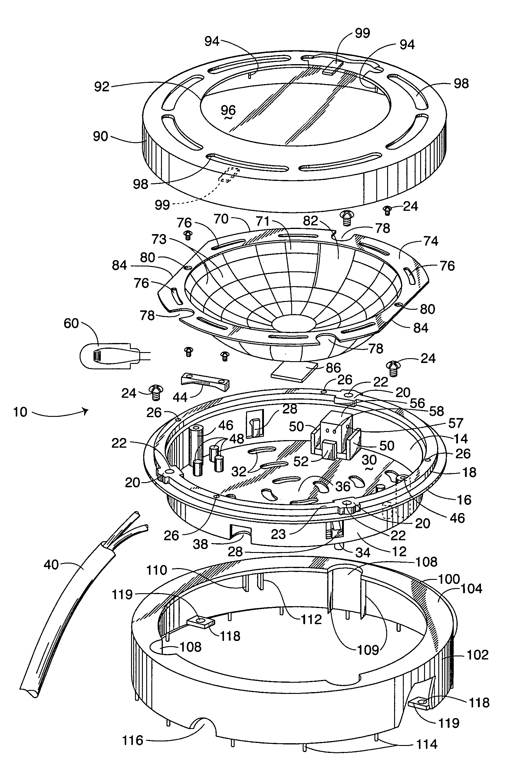
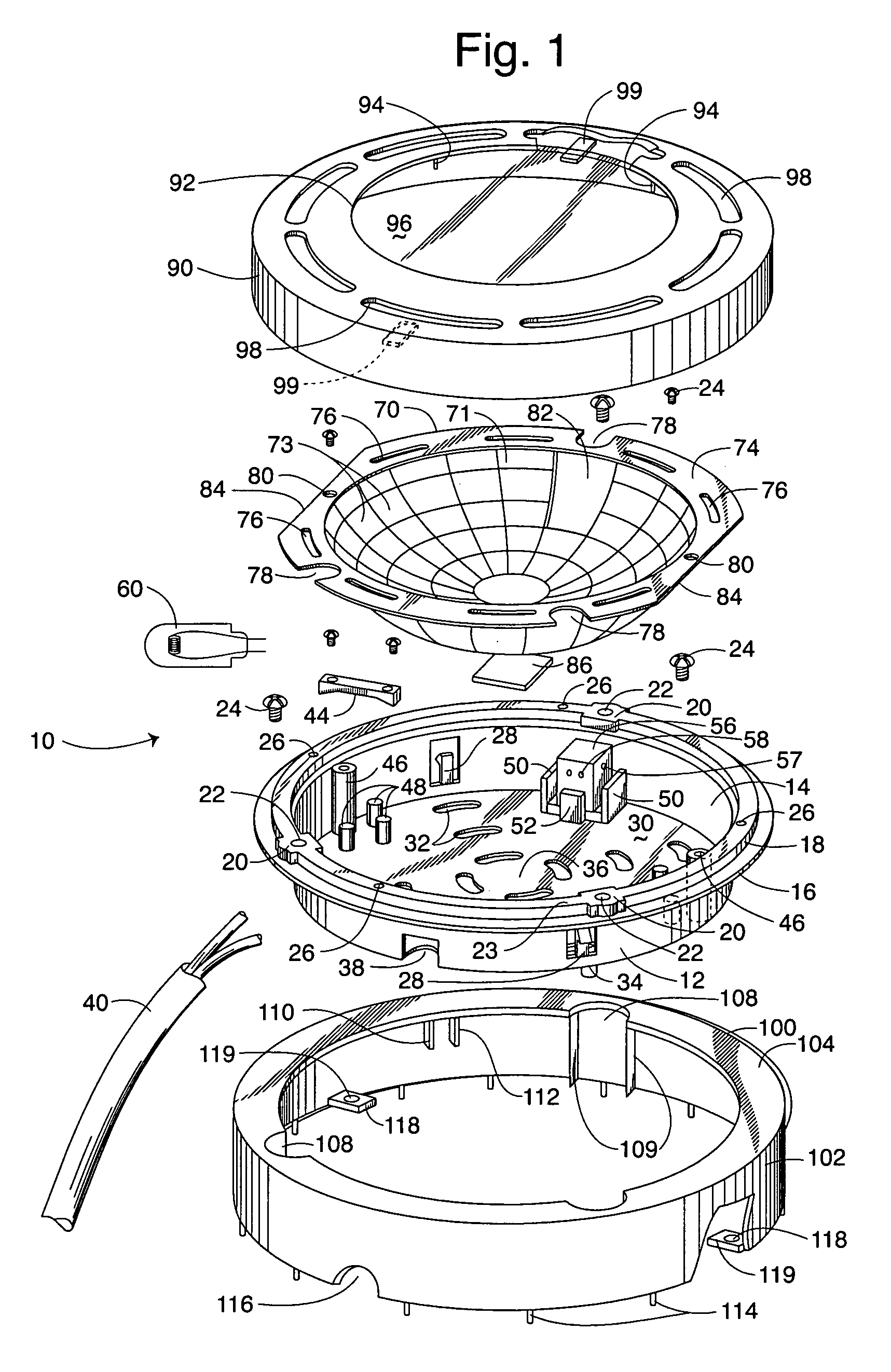
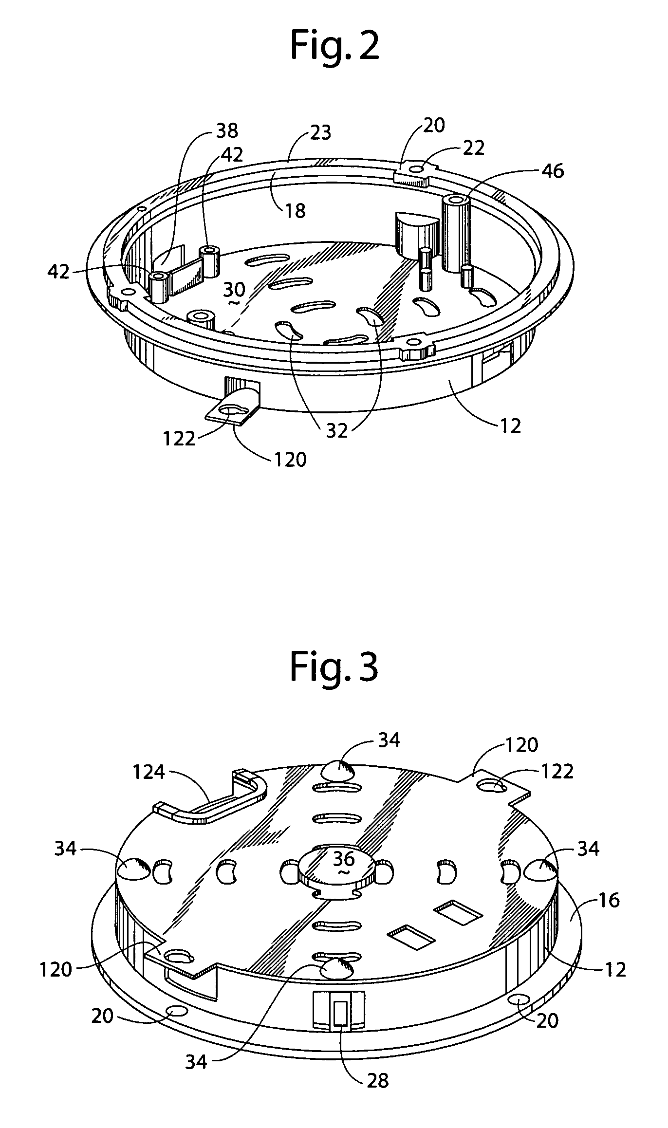
[0016]Referring now in more detail to the drawings in which like parts have like identifiers, FIG. 1 illustrates in exploded perspective view a light fixture 10 according to the present invention. The light fixture 10 readily mounts as an under-cabinet lighting fixture or recessed mounting, as discussed below. The light fixture 10 comprises a housing 12 having an open end 14 with a flange 16 extending laterally therefrom. The flange 16 is spaced-apart from an edge of the housing at the open end. As a result, a ridge or wall 18 extends around the edge from a first surface of the flange 16 longitudinally relative to the housing 12. The wall 18 defines thickened portions 20 that each defines a hole 22. As best illustrated in FIG. 4, each hole 22 is recessed so that a threaded screw 24 received in the hole 22 sits flush with a distal surface 23 of the wall 18. Four stops 26 extend laterally from a outward side of the wall 18. A pair of opposing tabs 28 are defined in a side wall of the ...


PUM


Abstract

A lighting fixture having a housing with a base and an opposing openable end, and a flange spaced-apart from an edge at the openable end that extends radially from an exterior surface of the housing. A reflector defines a dished cavity and seats on the edge of the housing, thereby defining a recess between an edge portion of the reflector and the flange. A light source is received within the housing. A light transmissive cover received on the housing has a tab received in the recess for guiding the rotation of the cover thereon.

Description

TECHNICAL FIELD[0001]The present invention relates to under-cabinet lighting fixtures. More particularly, the present invention relates to puck-type under-cabinet lighting fixtures which are readily installed with a cap to provide lighting from mounting surfaces.BACKGROUND OF THE INVENTION[0002]Lights and lighting provide useful general illumination of interior and exterior spaces in homes and buildings, as well as ornamental and artistic treatments for decorative purposes. These purposes include lighting functions for accent and interior ornamental design functions, highlights for artwork, illuminating work areas, and other functions. Often furniture or cabinetry have lights for illuminating articles held within the furniture or cabinets. For cabinets, and in particular kitchen wall cabinets, lighting fixtures are often mounted to a lower exterior surface or recessed therein, for illuminating countertop surfaces below the cabinets.[0003]One type of lighting fixture is known as an u...

Claims


Application Information

Patent Timeline
IPC IPC(8): F21S8/02F21S8/04F21V15/01F21V21/00F21V29/00F21V33/00
CPCF21S8/02F21S8/04F21V29/83F21V29/004F21V33/0012F21V15/01
Inventor BENENSOHN, SANFORD H.
Owner LUSA LIGHTING
Why Eureka
Try Eureka