Stapler with a leg-cutting device

a cutting device and leg technology, applied in the field of staplers, can solve the problems of inconvenient use of staplers with conventional leg cutting devices, affecting the convenience of etc., and achieve the effect of convenient cutting off excess portions of staple legs

Inactive Publication Date: 2006-01-03
APEX MFG
View PDF12 Cites 23 Cited by
  • Summary
  • Abstract
  • Description
  • Claims
  • Application Information

AI Technical Summary

Benefits of technology

[0007]The main objective of the invention is to provide a stapler that can cut off excess portions of staple legs conveniently. The stapler has a main base, a pivotal base, a recoiling device, a stapling device, a connecting device and a leg-cutting device. The pivotal base is pivotally attached to the main base with a first pivot. The recoiling device is mounted between the main base and the pivotal base to push the pivotal base to an original position. The stapling device is attached to the pivotal base and has a connecting bracket, a staple magazine, a handle assembly and a driving tab. The connecting bracket is attached to the pivotal base. The staple magazine is pivotally attached to the connecting bracket to receive multiple staples inside the staple magazine. The handle assembly is connected to the staple magazine. The driving tab is connected to the handle assembly and extends into the staple magazine. The connecting device is mounted between the main base and connecting bracket to rotate the pivotal base downward when the handle assembly is pressed. The leg-cutting device is mounted between the main base and the pivotal base and has an u...

Problems solved by technology

Furthermore, the movement of the bending arms of the conventional leg-cutting device is in a curved path, and to cut off the legs with the curved movement of the bending arms takes a large force.
In...

Method used


Image

  • Stapler with a leg-cutting device
  • Stapler with a leg-cutting device
  • Stapler with a leg-cutting device

Examples


Embodiment Construction

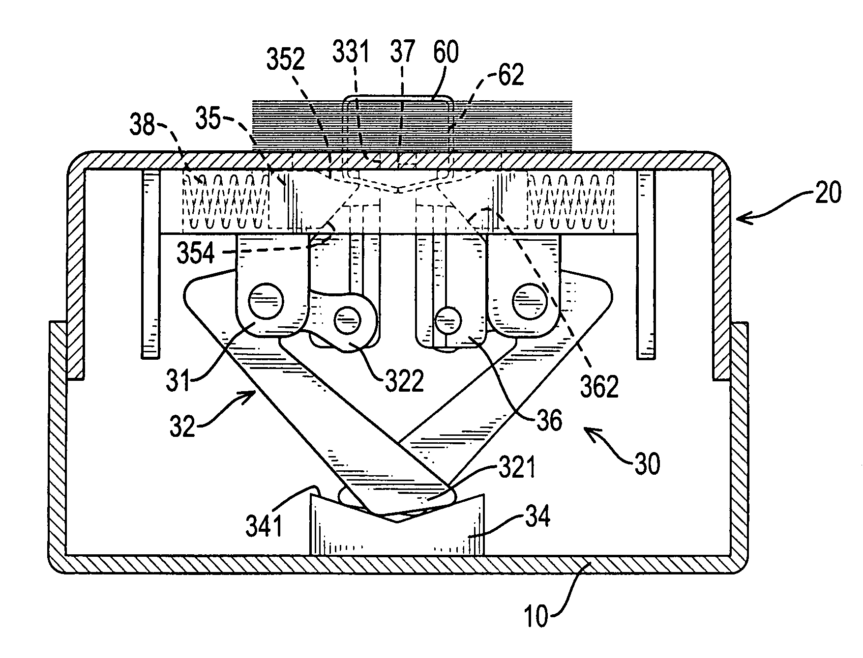
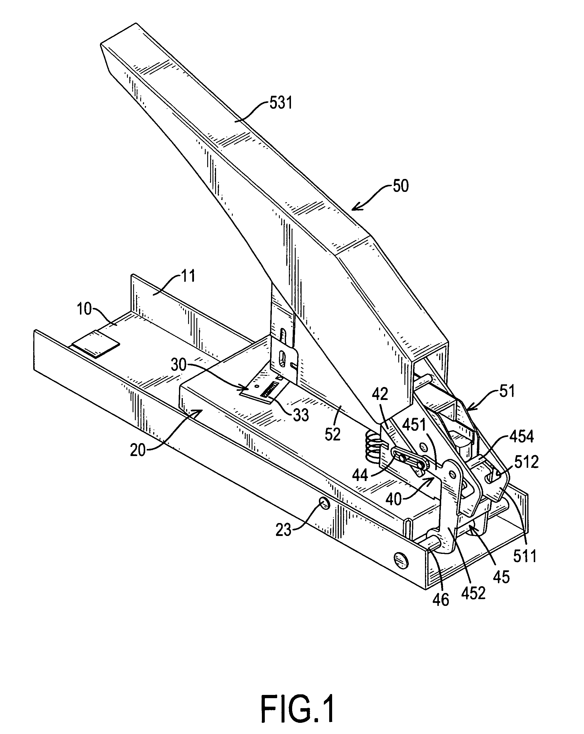
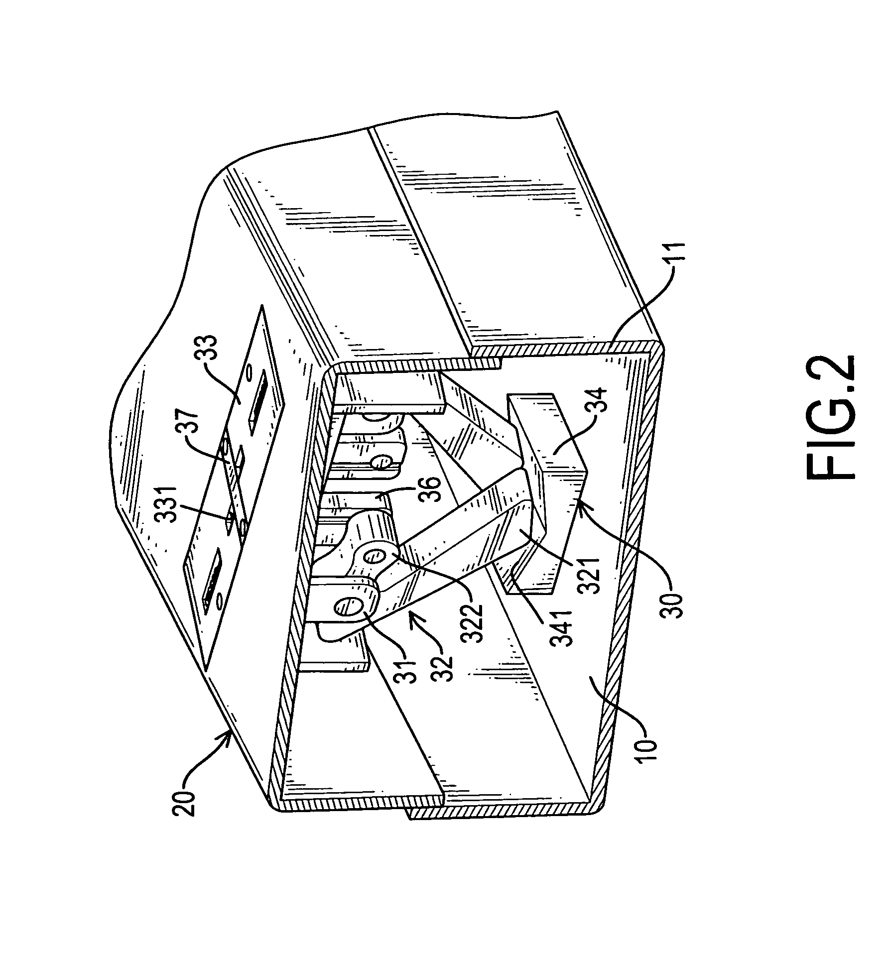
[0018]With reference to FIGS. 1 to 3, a stapler in accordance with the present invention comprises a main base (10), a pivotal base (20), a recoiling device (22), a leg-cutting device (30), a connecting device (40) and a stapling device (50). The main base (10) is U-shaped and has two wings (11).

[0019]The pivotal base (20) is pivotally attached to the main base (10) between the wings (11) with a first pivot (23). The recoiling device (22) is mounted between the main base (10) and the pivotal base (20) to push the pivotal base (20) to an original position. In a preferred embodiment, the recoiling device (22) is a spring.

[0020]The stapling device (50) is attached to the pivotal base (20) and comprises a connecting bracket (51), a staple magazine (52), a handle assembly (53) and a driving tab (54). The connecting bracket (51) is attached to the pivotal base (20) and comprises two side plates (511) parallel with each other. Each side plate (511) has a positioning channel (512) aligning ...


PUM


Abstract

A stapler has a main base, a pivotal base, a recoiling device, a stapling device, a connecting device and a leg-cutting device. The leg-cutting device is mounted between the main base and the pivotal base and has an upper base, a lower base, two arm holders, two pushing arms, a cutting pad, two cutting blocks, two guiding blocks and two biasing members. The lower base has an arm-lifting top surface. The pushing arms are pivotally connected to the arm holders and each has a sliding end slidably attached to the arm-lifting top surface of the lower base and a pushing end. The cutting blocks are attached respectively to the pushing ends of the pushing arms. The guiding blocks are slidably mounted on the pivotal base and are driven by the cutting blocks.

Description

BACKGROUND OF THE INVENTION[0001]1. Field of the Invention[0002]The present invention relates to a stapler, and more particularly to a stapler with a leg-cutting device whereby legs of a staple can be bent and excess portions cut off.[0003]2. Description of Related Art[0004]A stapler is an important office tool and is used to bind multiple document sheets together with a staple. However, the amount of sheets to be stapled may vary considerably such that the thickness of the pile needs to be taken into special consideration. Thus, a stapler is commonly supplemented with a leg-cutting device to cut off redundant parts of legs of a staple. With reference to FIG. 9, a conventional leg-cutting device substantially comprises two pivotal bending arms (80) and a cutting pad (82). Each bending arm (80) has a bending surface (802) formed on the top. When a user uses a stapler with the conventional leg-cutting device and presses a handle of the stapler downward, a stapler will be pushed out of...

Claims


Application Information

Patent Timeline
IPC IPC(8): B27F7/23
CPCB25C5/0242B25C5/0207
Inventor TSAI, ERIC
Owner APEX MFG
Why Eureka
Try Eureka