Visual latching indicator arrangement for an electrical bushing and terminator
What is Al technical title?
Al technical title is built by PatSnap Al team. It summarizes the technical point description of the patent document.
a technology of latching indicator and electrical bushing, which is applied in the direction of coupling base/case, coupling device connection, insulating body, etc., can solve the problem of difficulty for operators to visually d
Inactive Publication Date: 2006-01-10
COOPER TECH CO
View PDF64 Cites 72 Cited by
Summary
Abstract
Description
Claims
Application Information
AI Technical Summary
This helps you quickly interpret patents by identifying the three key elements:
Problems solved by technology
Method used
Benefits of technology
Problems solved by technology
That unlatched condition, which is potentially dangerous, is difficult for the operator to visually detect, especially since the operator will likely be standing remotely (e.g., at least three to five feet) from the terminator and bushing, for safety reasons.
Method used
Image
Click on the blue label to locate the original text in one second.
Reading with bidirectional positioning of images and text.
Examples
Embodiment Construction
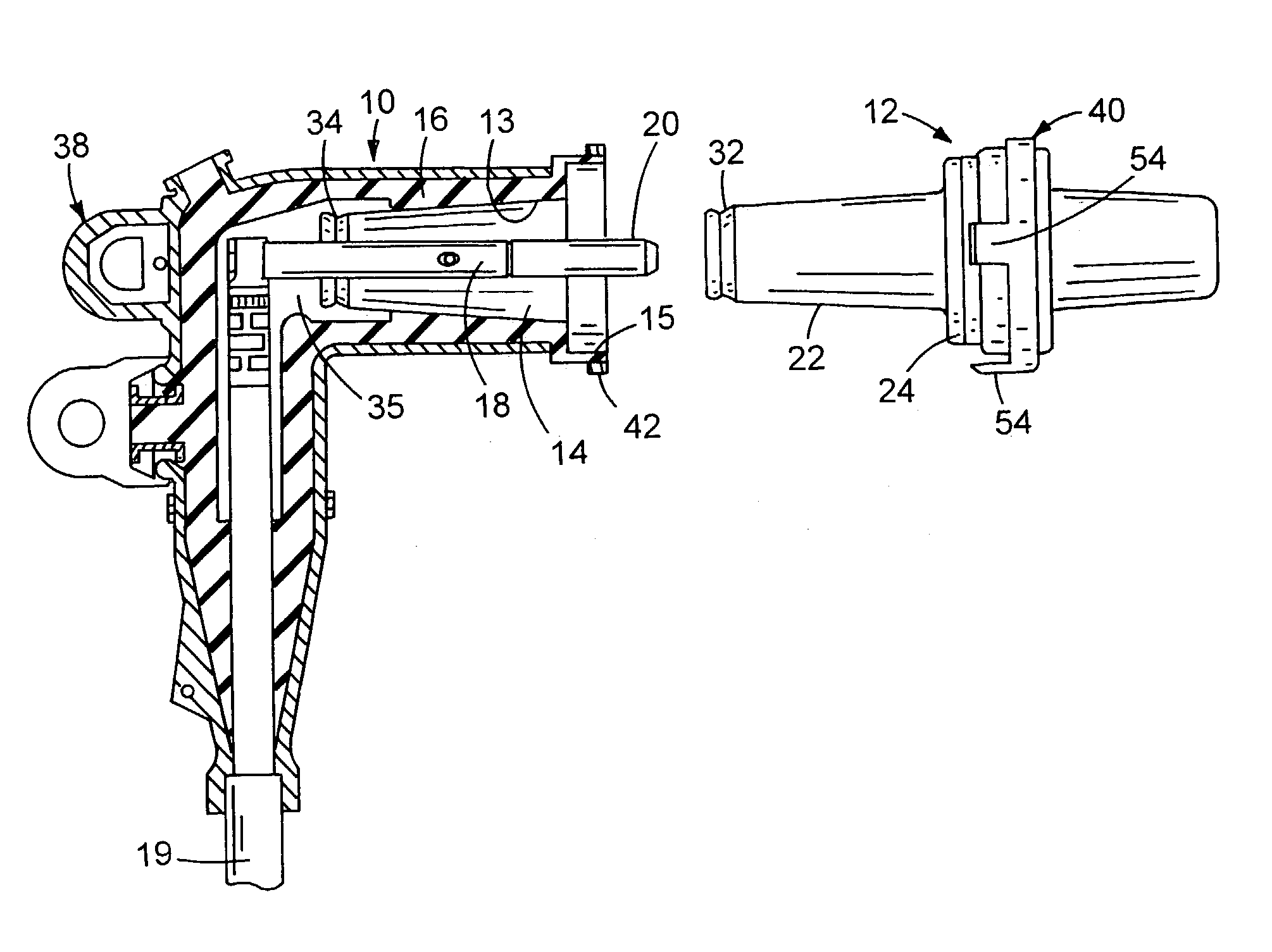
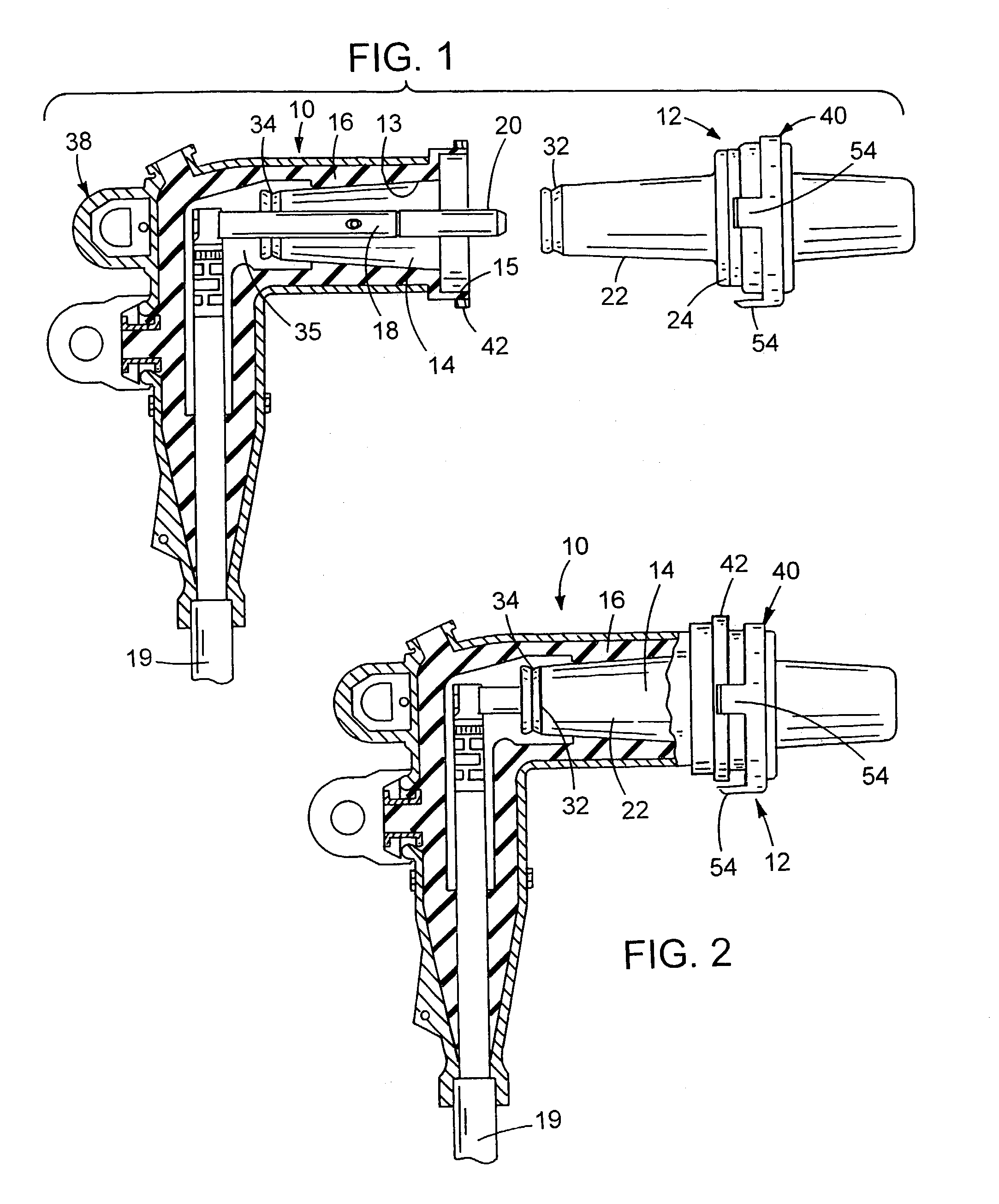
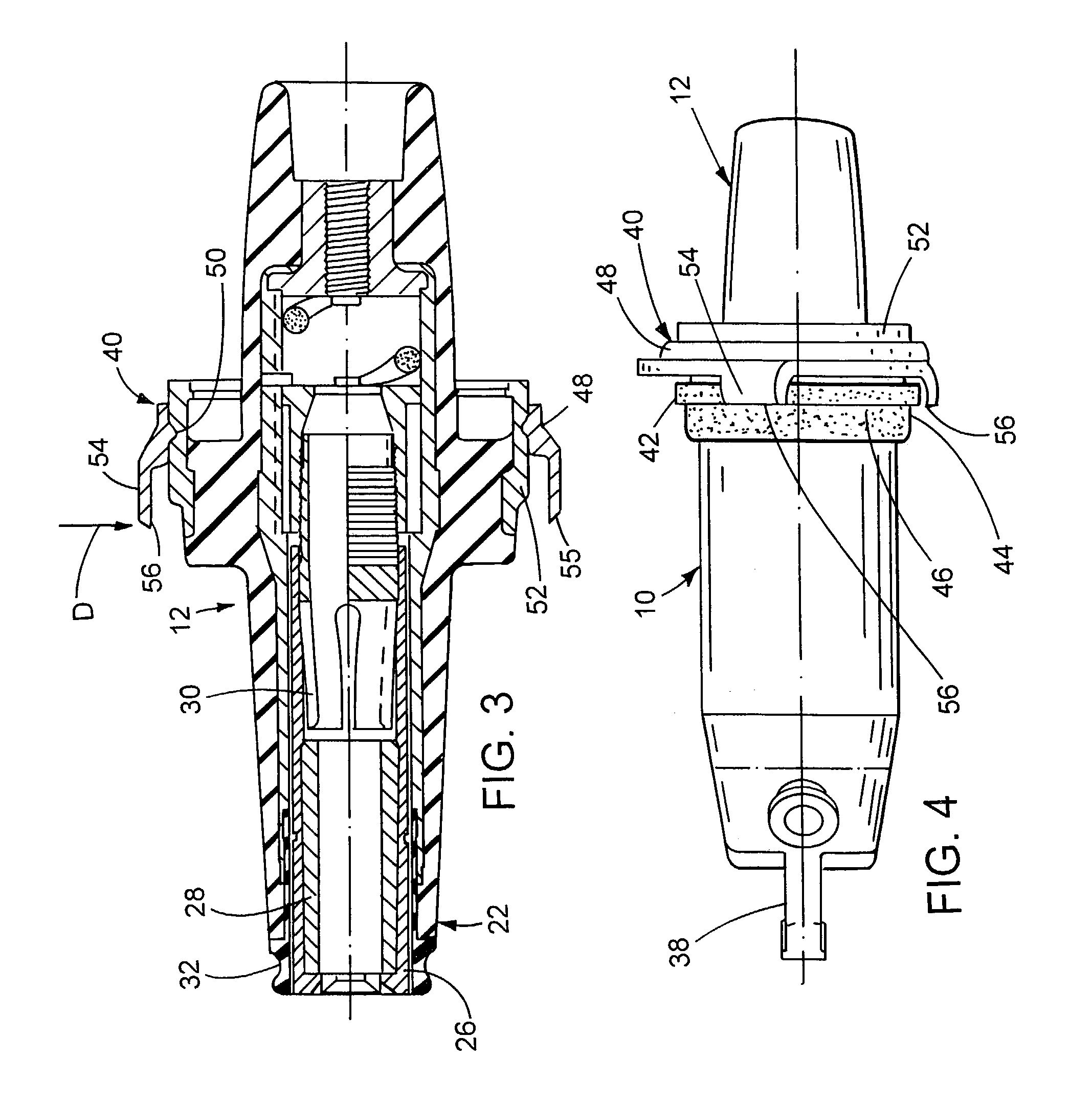
[0018]Depicted in FIG. 1 is a loadbreak elbow terminator 10 and a bushing 12 adapted for connection therewith. The bushing can be of a type which is fixed to a stationary panel such that a tongue 22 is externally exposed. The elbow terminator includes a socket 14 formed in an electrical insulative material 16. The socket 14 includes a tapered portion 13 and merges into a cylindrical portion 15. Extending centrally along the socket is a probe 18 which carries an arc follower 20. The probe 18 is electrically connected to a cable 19.
[0019]The tongue 22 is configured to make an interference fit within the socket 14. Adjoining the tongue 22 is a cylindrical enlargement 24 configured to enter the cylindrical portion 15. The tongue 22 is hollow and includes a contact tube 26 (see FIG. 3) in which are disposed an arc interrupter 28 and a contact sleeve 30.
[0020]An end of the tongue 22 includes a latching groove 32. When the elbow terminator is pushed onto the bushing 12, the latching groove...
PUM
Property
Measurement
Unit
distance
aaaaa
aaaaa
distance
aaaaa
aaaaa
depth
aaaaa
aaaaa
Abstract
An elbow terminator has a socket in which an electrical probe is disposed. The terminator is insertable onto an electrical bushing such that a tongue of the bushing is received in the socket of the terminator, and the probe of the terminator is electrically coupled to a contact sleeve disposed within the tongue. A latching mechanism produces positive latching between the tongue and socket when the tongue has been inserted to a predescribed depth within the socket. In order to enable an operator to visually observe that the tongue has been inserted to the prescribed depth, the bushing carries a color band which becomes completely disposed (invisible) in the socket when positive latching occurs. Alternatively, the bushing can be provided with gauge tabs which become aligned with a witness line formed on the terminator when positive latching occurs.
Description
RELATED INVENTION[0001]This application is a continuation of U.S. Ser. No. 10 / 198,963, filed Jul. 22, 2002, now abandoned; which is a continuation of U.S. Ser. No. 08 / 821,760, filed Mar. 20, 1997, now U.S. Pat. No. 6,504,103; which is a continuation of U.S. Ser. No. 08 / 262,460, filed Jun. 20, 1994, now abandoned; which is a continuation-in-part of U.S. Ser. No. 08 / 038,335, filed Mar. 10, 1993, now abandoned, all of which are incorporated by reference.BACKGROUND OF THE INVENTION[0002]The present invention relates to the interconnection of electrical distribution elements and, in particular, to the interconnection between a loadbreak elbow terminator and a bushing.[0003]Electrical distribution equipment, such as a deadfront switch gear arrangement, typically includes fixed electrical bushings which are to be connected to external electrical cables. The fixed bushings are mounted in a wall of the electrical equipment and have their outer ends arranged to be connected to the cables.[000...
Claims
Application Information
Patent Timeline
Application Date:The date an application was filed.
Publication Date:The date a patent or application was officially published.
First Publication Date:The earliest publication date of a patent with the same application number.
Issue Date:Publication date of the patent grant document.
PCT Entry Date:The Entry date of PCT National Phase.
Estimated Expiry Date:The statutory expiry date of a patent right according to the Patent Law, and it is the longest term of protection that the patent right can achieve without the termination of the patent right due to other reasons(Term extension factor has been taken into account ).
Invalid Date:Actual expiry date is based on effective date or publication date of legal transaction data of invalid patent.
Patent Type & Authority Patents(United States)
IPC IPC(8): H01B17/58
CPCH01R13/53H01R13/641Y10S439/921
Inventor MEYER, ANDREW E.KNAPP, TODD KIMMUENCH JR., FRANK J.