Syringe, in particular for veterinary applications

a technology of syringes and syringes, which is applied in the field of syringes, can solve the problems of unsatisfactory discharge of fluid through the discharge outlet, and achieve the effect of reducing expenditur

Active Publication Date: 2006-01-24
HENKE SASS WOLF +1
View PDF11 Cites 15 Cited by
  • Summary
  • Abstract
  • Description
  • Claims
  • Application Information

AI Technical Summary

Benefits of technology

[0008]Thus, the invention no longer uses two independent check valves, but the closing of the discharge outlet and the opening of a filling opening, through which the syringe barrel may be filled with fluid from the fluid container, is effected by means of one single valve member moving between two positions. Accordingly, the closing of the discharge outlet and the opening of the supply opening for fluid flowing into the syringe barrel is effected by one single valve member, so that the occurrence of problems with differently responding check valves, each equipped with independent valve members, is positively eliminated. Moreover, a considerable simplification is achieved, because only one valve is required, which now serves the function of the two valves present in the prior art.
[0028]The signal from the magnetic field sensor makes it possible to very simply provide a control unit causing the syringe barrel to be filled when the output signal indicates a maximally advanced plunger in the syringe barrel.

Problems solved by technology

In particular, in the aforementioned second type of syringes, which are filled via a fluid container connected therewith, there may occur, during a filling operation, an undesired discharge of fluid through the discharge outlet, which is generally caused by the response behavior of the two check valves.

Method used


Image

  • Syringe, in particular for veterinary applications
  • Syringe, in particular for veterinary applications
  • Syringe, in particular for veterinary applications

Examples


Embodiment Construction

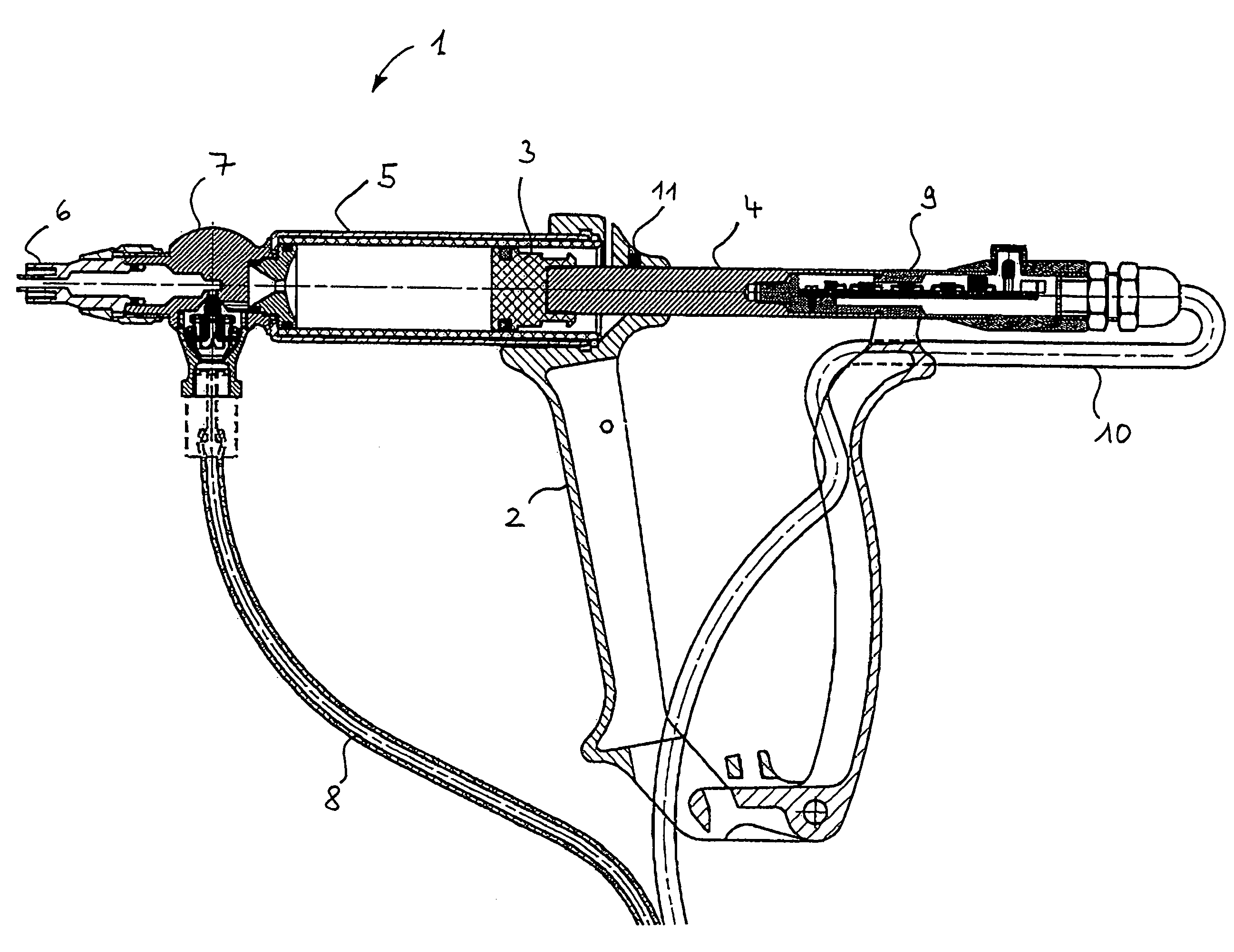
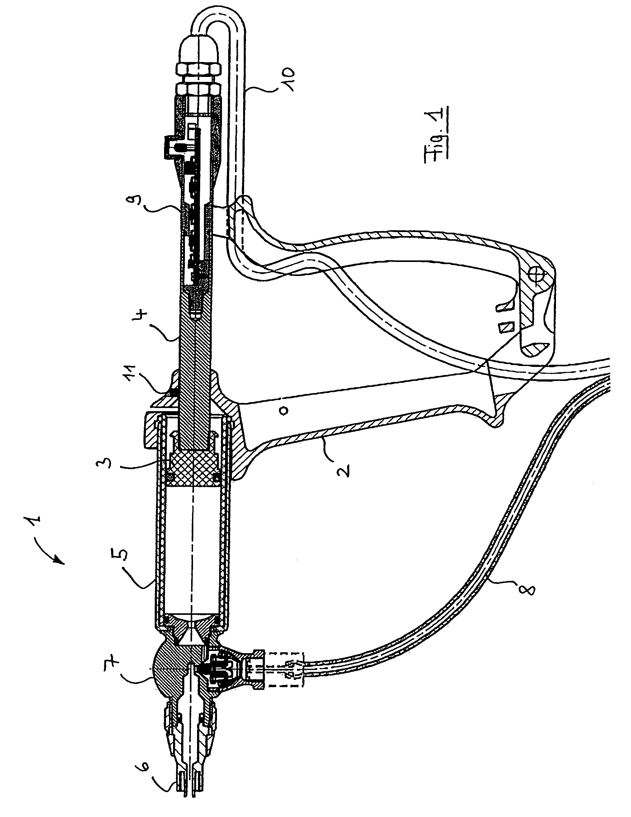
[0036]FIG. 1 shows a veterinary syringe 1 in a sectional representation. The syringe 1 comprises a handle 2 having applied thereto a lever by which the syringe can be actuated. Actuation of the lever acts on a plunger 3 which is attached to a plunger rod 4 and moves inside a barrel 5. The syringe further comprises a port 6 onto which a syringe needle may be fitted. A port 6 is screwed onto a syringe head 7 by means of an intermediate ring. On an opposite side, a barrel 5 is screwed into the head using a suitable gasket. Further, a supply duct 8 from a fluid container (not shown in FIG. 1), which is connected to a fluid container port of the syringe head 7, terminates in the syringe head 7 via a valve mechanism without a reference numeral in FIG. 1, which will be explained later.

[0037]A position-sensing device 9, which is electrically connected via a signal cable and cooperates with a magnet 11 provided at the end of the handle 2 into which the syringe barrel is inserted, in order to...


PUM


Abstract

A syringe for connection to a fluid container containing fluid to be discharged comprises a syringe barrel with a plunger moving therein, and a discharge outlet, through which fluid contained in the fluid container is dischargeable by actuation of the plunger, said syringe barrel being connected with the fluid container port and the discharge outlet via a fluid channel system, and a valve mechanism being provided in the fluid channel system, allowing the syringe barrel to be filled with fluid from the fluid container and to then discharge said fluid through the discharge outlet, wherein the valve mechanism comprises a valve member which is movable between first and second positions, said valve member, in said first position, allowing fluid flow from the fluid container to the syringe barrel and simultaneously blocking fluid flow from or to the discharge outlet and, in said second position, allowing fluid flow from the syringe barrel to the discharge outlet while simultaneously blocking fluid flow from or to the fluid container.

Description

RELATED APPLICATION[0001]This application claims priority to German Patent Application No. 103 26 306.3 filed Jun. 11, 2003.TECHNICAL FIELD[0002]The invention relates to a syringe comprising a fluid container port for a fluid container containing fluid to be discharged, a syringe barrel with a plunger moving therein, and a discharge outlet, through which fluid supplied by actuation of the plunger in the fluid container port is dischargeable, said syringe barrel being connected with the fluid container port and the discharge outlet via a fluid channel system, and a valve mechanism being provided in the fluid container port, allowing the syringe barrel to be filled with fluid supplied at the fluid container port and to then discharge said fluid through the discharge outlet.BACKGROUND OF THE INVENTION[0003]Particularly in veterinary applications, syringes are known which allow a syringe barrel to be filled repeatedly from a fluid container and to discharge the drawn fluid manually from...

Claims


Application Information

Patent Timeline
Patent Type & Authority Patents(United States)
IPC IPC(8): A61M5/00A61M5/178A61D1/02A61M5/20A61M5/31A61M5/315
CPCA61D1/025A61M5/3148A61M5/204A61M5/31581A61M5/31525A61M5/31573
Inventor SCHREIJAG, KARLKIEHN, RALF
Owner HENKE SASS WOLF
Why Eureka
Try Eureka