Dental implant and method of insertion

a dental implant and implant technology, applied in the field of dental implants and methods of insertion, can solve problems such as fractures and breaks of implants, and achieve the effects of low stress isoelastic integration, high resistance to fatigue and breakage, and rapid and stable insertion

Inactive Publication Date: 2006-01-31
BIOMED EST
View PDF18 Cites 22 Cited by
  • Summary
  • Abstract
  • Description
  • Claims
  • Application Information

AI Technical Summary

Benefits of technology

[0012]An aspect of the present invention is to provide a dental implant having implant geometry which allows rapid, low-stress isoelastic integration of the implant into the jaw bone while assuring that the basally osseointegrated implant is highly resistant to fatigue and breakage.
[0014]A method of inserting a one-piece dental implant for endosteal and combined endosteal / subperiosteal osseointegration into an alveolar bone with a vestibular side and a palatal side includes the steps of providing a one-piece dental implant having a force-transferring foot part for insertion into the alveolar bone and a post that projects out of the alveolar bone; inserting the dental implant into the vestibular side of the alveolar bone; securely engaging the dental implant in the palatal side of the alveolar bone, leaving a part of the dental implant protruding from the vestibular side of the alveolar bone; bending and adapting the protruding part of the dental implant to the vestibular side of the alveolar bone; or trimming extraneous parts of the dental implant.
[0015]While crestal implants, i.e., screws and cylinder implants, are made rigid by the manufacturer according to the specifications, and so, together with the bridges mounted on them, give rigid implant prosthetic systems, the one-piece, basally osseointegrated implants according to an embodiment of the present invention make possible an approximately isoelastic connection between the compact jaw bone and the denture. Thus the bending forces that arise are better accepted because of the geometry of the base part and are distributed more evenly over the whole base part with lower peak stresses.
[0017]Because of the implant geometry described, it is also possible to provide approximately isoelastic connections between bone and implant, in which the bone adapts to the elasticity of the implant by altering the matrix, changing the degree of mineralization and enlarging load transferring areas by bone induction. That happens extraordinarily successfully with the implant described.
[0018]The implant geometry described and the implants produced using it allow an isoelastic bond to the compact and spongy jaw bones. That avoids both force peaks with osteolytic effect and excessive movement of the implant with the potential consequences of osteolyses due to mobility, and inflammation of the connective tissue. That, though, requires a special distribution of stress from the forces being absorbed by the implant and transferred to the jaw in the vicinity of the framework, of the post, of the transition between the post and the framework, and in the transition to the abutment or bridge.

Problems solved by technology

In very unfavorable cases, this can cause fractures and breaks in the implant due to peak stresses, especially in the base part.

Method used


Image

  • Dental implant and method of insertion
  • Dental implant and method of insertion
  • Dental implant and method of insertion

Examples


Embodiment Construction

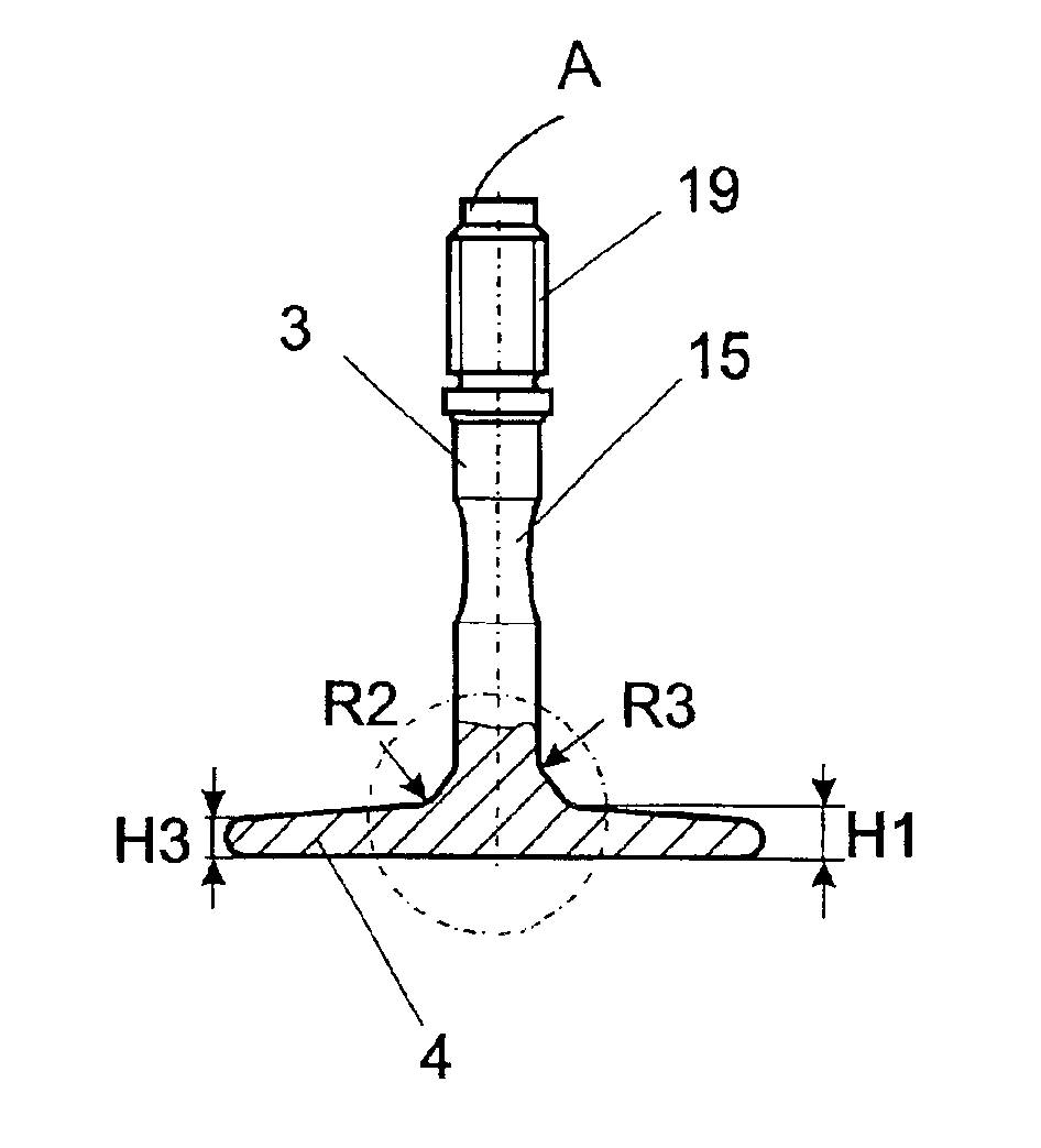
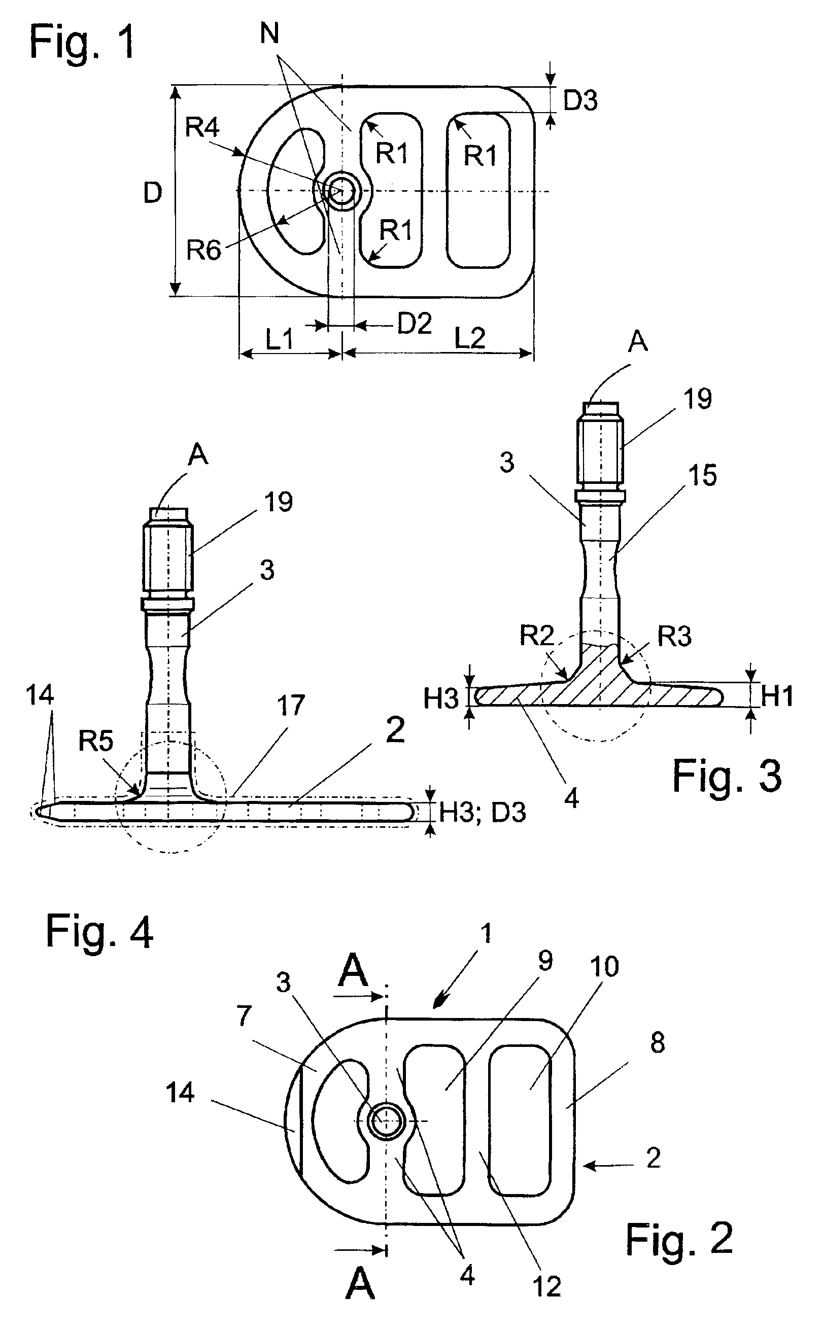
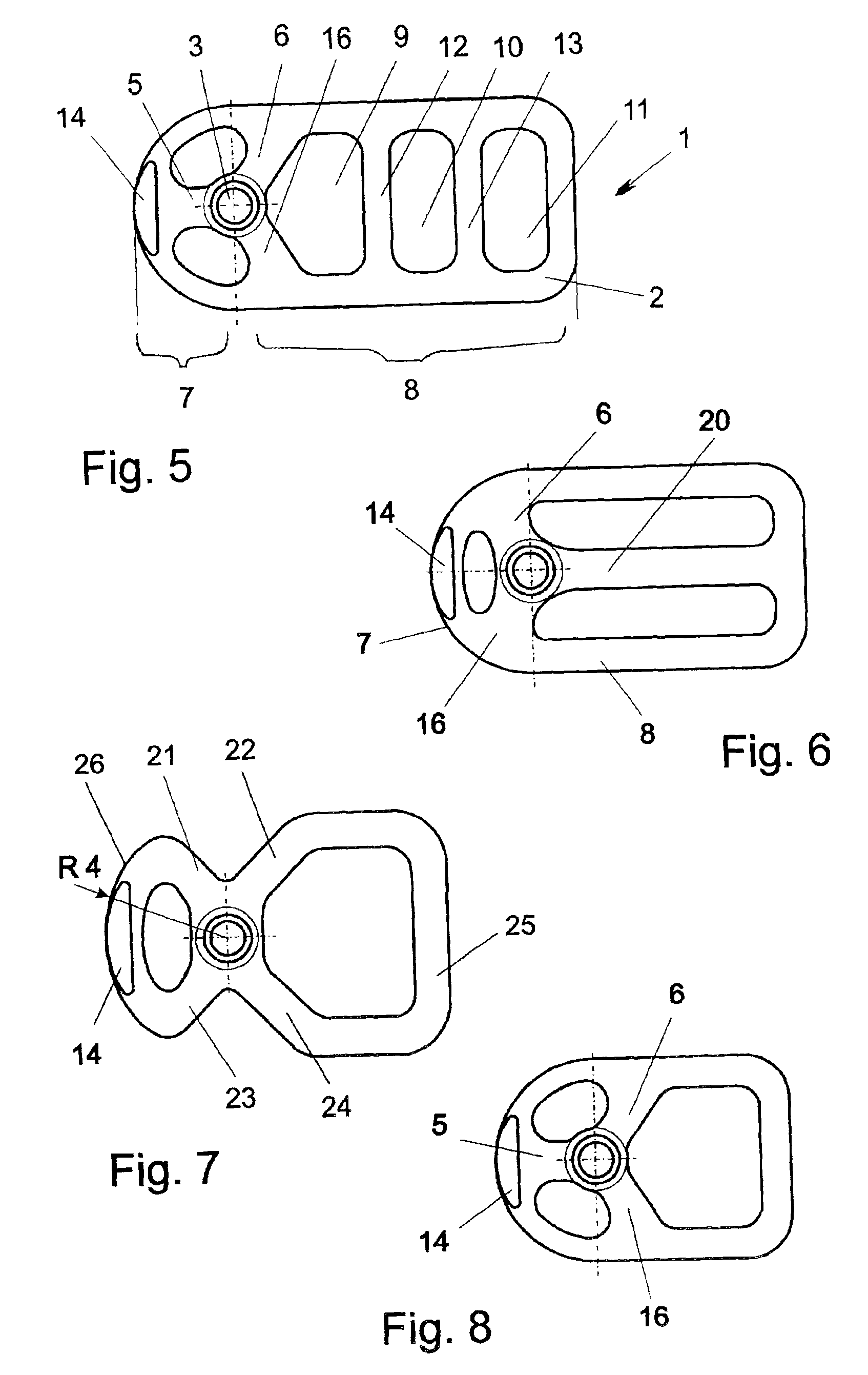
[0037]The first truly basally osseointegrated implants have been proposed in EP 0 935 949 A1, the disclosure of which is hereby incorporated by reference. They are different from implants, which either have a totally rigid design or transfer forces through expanded surfaces along the vertical post (e.g., FR 2,302,715). On the basis of these basally osseointegrated implants, it is possible to provide strategic implant positioning independently of the presence of a vertical bone supply and to provide basally osseointegrated implant prosthetic systems. For example, the annular design of the base part and the connection of the base part to the post through bars has the advantage that, if high forces are applied, the post can deflect slightly into the spongiosa, while the annular base remains solidly anchored in the compacta, supporting a lasting solid seating of the implant in the jaw bone. Further, the positioning of the post outside the center of the base part, in the center of the se...


PUM


Abstract

A one-piece dental implant for endosteal and combined endosteal / subperiosteal osseointegration includes a force-transferring foot part for insertion into a jaw, the foot part including a frame in a closed geometric form having an interior open area and at least one bar connected with the frame and extending into the interior open area of the geometric form, said geometric form including at least a partial ring shape; a post that projects out of the jaw, said post connected with the foot part through the bar; and wherein a profile of the bar has a first height at a first transition region where it connects with the closed frame and a second height, which is greater than the first height, at a second transition region where it connects with the post, the height of the bar tapering from the second height to the first height.A method of inserting the disclosed one-piece dental implant for endosteal and combined endosteal / subperiosteal osseointegration into an alveolar bone with a vestibular side and a palatal side includes the steps of providing a one-piece dental implant having a force-transferring foot part for insertion into the alveolar bone and a post that projects out of the alveolar bone; inserting the dental implant into the vestibular side of the alveolar bone; securely engaging the dental implant in the palatal side of the alveolar bone, leaving a part of the dental implant protruding from the vestibular side of the alveolar bone; bending and adapting the protruding part of the dental implant to the vestibular side of the alveolar bone; and trimming extraneous parts of the dental implant.

Description

CROSS REFERENCE TO RELATED APPLICATIONS[0001]This application is a continuation-in-part of U.S. application Ser. No. 09 / 829,351 filed Apr. 9, 2001, now U.S. Pat. No. 6,402,516, which is a continuation of U.S. application Ser. No. 09 / 437,643 filed Nov. 10, 1999, now abandoned, which claimed priority of German Application No. 298 20 487.8 filed on Nov. 11, 1998, German Application No. 299 08 207.5 filed on May 4, 1999, and European Application No. 99 250 289.8 filed on Aug. 25, 1999. This application also claims priority of German Application No. 202 02 424.5 filed on Feb. 14, 2002.TECHNICAL FIELD OF THE INVENTION[0002]The invention relates generally to dental prosthetics and, more particularly, to a dental implant for endosteal and combined endosteal / subperiosteal basal osseointegration and to a method of inserting such an implant.DESCRIPTION OF THE RELATED ART[0003]Dental screw, blade, and cylinder implants which osseointegrate along the vertical axis of the implant are already know...

Claims


Application Information

Patent Timeline
Patent Type & Authority Patents(United States)
IPC IPC(8): A61C8/00
CPCA61C8/001A61C8/0018A61C8/0031
Inventor IHDE, STEFAN
Owner BIOMED EST
Why Eureka
Try Eureka