Waste mud agitation system

a waste mud and agitation system technology, applied in the direction of mixing, transportation and packaging, well accessories, etc., can solve the problems of heavy and dirty work, and settle on the bottom of the tank, so as to promote efficient dumping and eliminate the effect of heavy and messy shoveling of sludg

Inactive Publication Date: 2006-02-14
GALLUP GORDON LEROY
View PDF25 Cites 6 Cited by
  • Summary
  • Abstract
  • Description
  • Claims
  • Application Information

AI Technical Summary

Benefits of technology

[0004]It is an object of this invention to disclose a method to eliminate the heavy and messy shovelling of sludge from a waste mud hauling truck. It is an object of this invention to eliminate the most disliked part of a waste truck driver's job turnover. It is a final object of this invention to promote efficient dumping.
[0005]One aspect of this invention provides for a method of facilitating more complete removal of waste drilling mud having core material therein from a tank comprising the step of pumping mud taken from within the tank through a permanently mounted nozzle within the tank, said nozzle directed at mud on a bottom portion of the tank to agitate settled core material once suspended in the mud.

Problems solved by technology

One common problem with this equipment and method of waste mud disposal is that the suspended core material in the waste mud settles on the tank bottom.
Removal of this muddy sludge is very time consuming.
It is also heavy and dirty work.
Particularly when there is shale in the mud, there is a substantial amount of sludge that will not run out of the tank, and a large amount of shovelling for the driver.

Method used


Image

  • Waste mud agitation system
  • Waste mud agitation system

Examples


Embodiment Construction

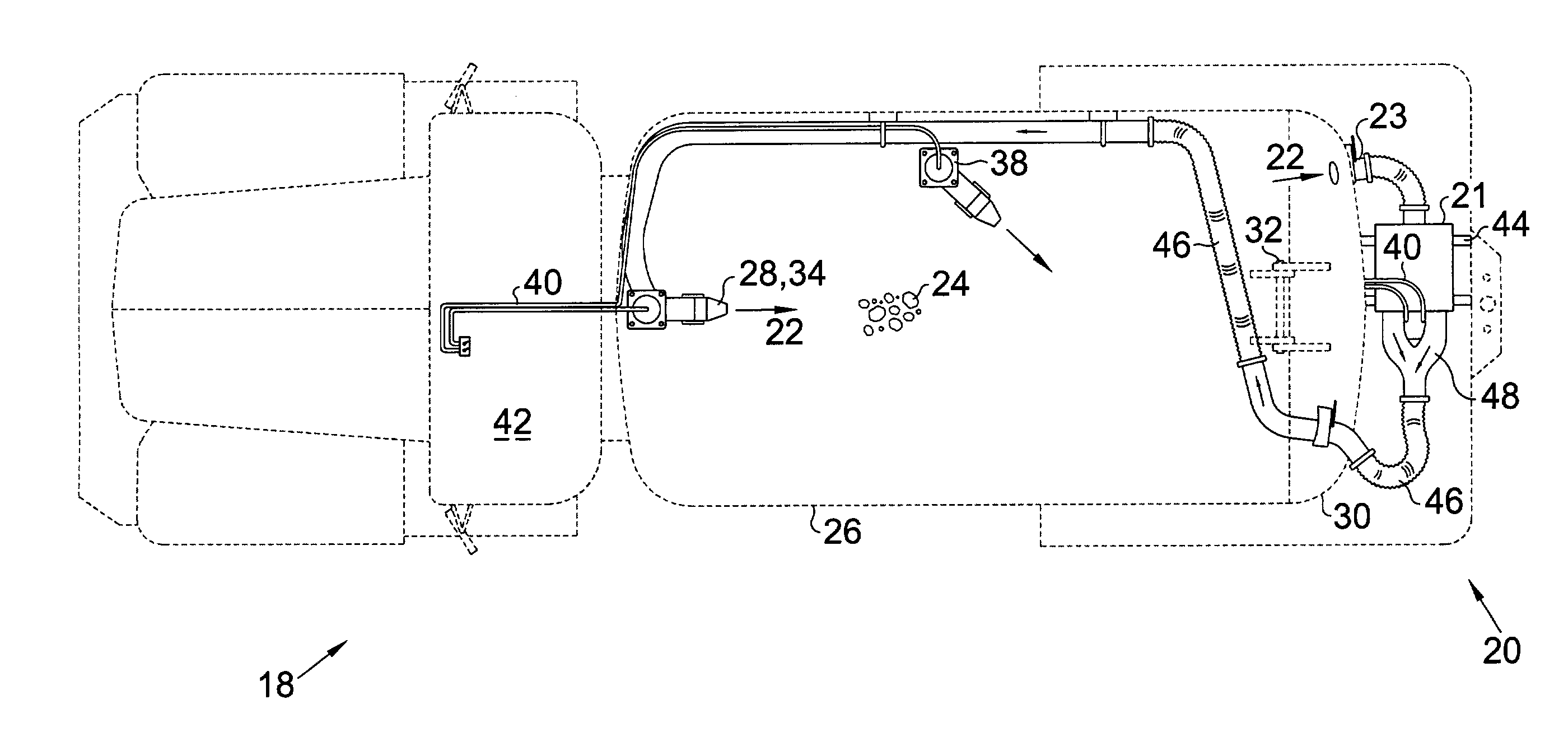
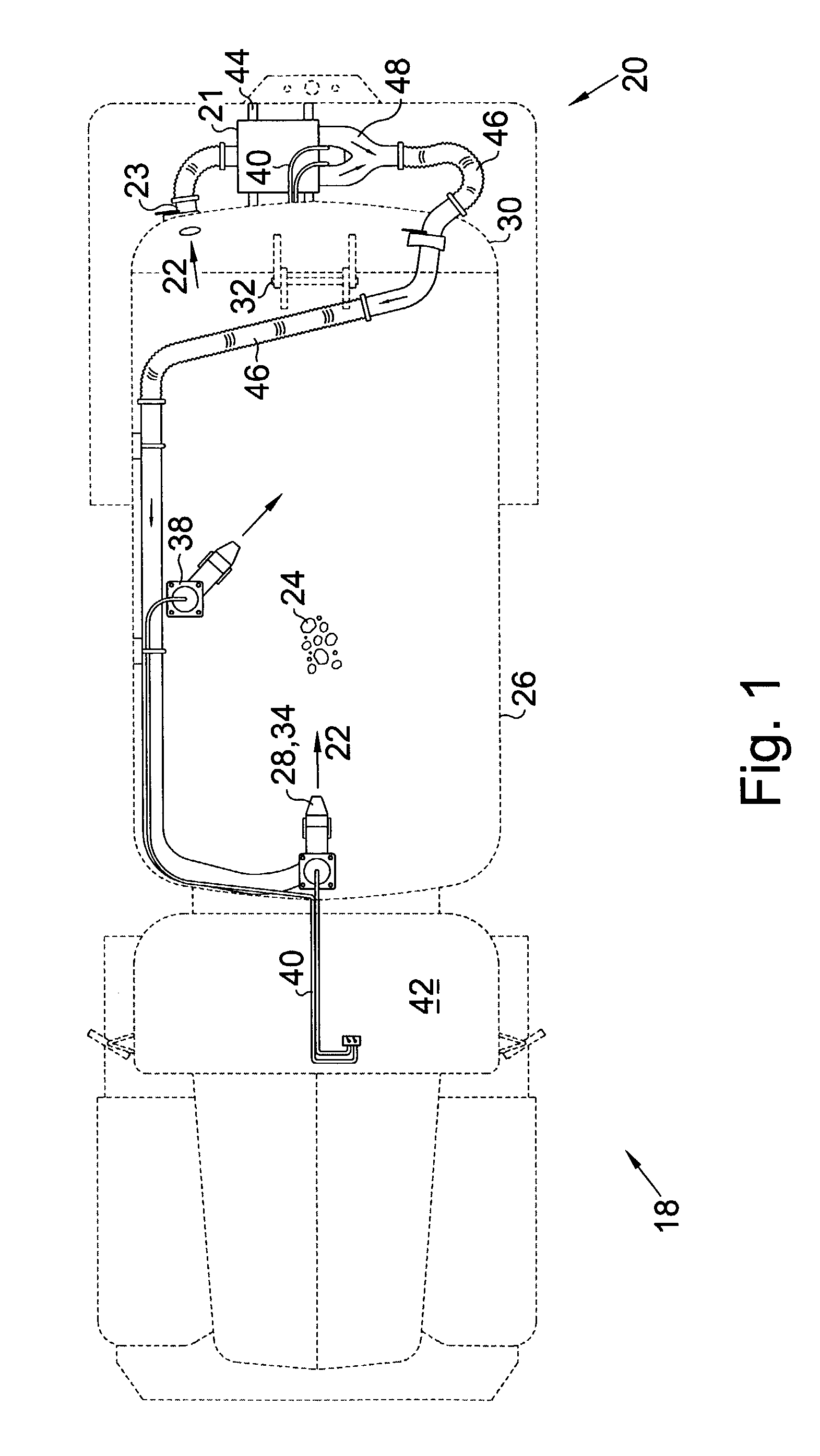
[0011]Turning now to the drawings and more particularly to FIG. 1 we have a plan view of a waste mud truck 18 fitted with a mud agitation system 20 to facilitate complete dumping of waste mud 22 having core material 24 therein. A method of facilitating more complete removal of waste drilling mud 22 having core material 24 therein from a tank 26 comprises the steps of: pumping 21 mud 22 taken from within the tank 26 through a permanently mounted nozzle 28 within the tank 26. Said nozzle 28 is directed at mud 22 on a bottom portion of the tank 26 to agitate settled core material 34 once suspended in the mud 22. The cylindrical tank 26 can accommodate both vacuum used to intake mud 22 and air pressure used to discharge mud 22.

[0012]In a preferred embodiment of the invention the tank 26 is cylindrical and longitudinally mounted on a truck 18 for waste mud hauling. The tank 26 has a rear end cap 30 which is hinged 32 to a top portion of the tank 26. When a front portion of the tank 26 is...


PUM


Abstract

An agitation system for a mud tank to prevent core material initially suspended in the drilling mud, from settling. The method agitates sludge and eliminates the need to hand shovel sludge from the tank after dumping. The method comprises the step of pumping mud taken from within the tank through a permanently mounted rubber nozzle directed at mud on a bottom portion of the tank. In a preferred aspect of this invention the tank is a cylindrical and longitudinally mounted on a truck for waste mud hauling, and has a rear end cap hinged to a top portion of the tank, so that when a front portion of the tank is marginally elevated and the end cap is hinged opened, mud dumps from a rear end portion of the tank.

Description

FIELD OF THE INVENTION[0001]This invention relates to removal of used drilling mud from petroleum drilling rigs. More particularly this invention relates to an agitation system for a vacuum mud tank truck. The system prevents core material, initially suspended in the drilling mud, from settling on the bottom of the tank on the mud truck.BACKGROUND OF THE INVENTION[0002]The inventor is engaged in the business of waste mud disposal. When a well is drilled, mud is pumped down the well hole to cool the cutting head and remove the core material which has been cut beneath the cutting head. The used drilling mud having core material suspended therein must be hauled away from the well site for disposal. The used mud having core material suspended therein is pumped into tank trucks to be hauled away. At a disposal location, a front portion of the tank on the tank truck is lifted a few feet and a rear end cap of the tank hinges open from a hinge on the tank top, then the waste mud within the ...

Claims


Application Information

Patent Timeline
Patent Type & Authority Patents(United States)
IPC IPC(8): B01F5/00B01F25/60E21B21/06
CPCE21B21/062B01F5/0206B01F25/21
Inventor GALLUP, GORDON LEROY
Owner GALLUP GORDON LEROY
Why Eureka
Try Eureka