Lift chair

a lift chair and chair technology, applied in the field of lift chairs, can solve the problems of relatively complex and expensive components of the wet obj

Active Publication Date: 2006-02-21
BRESSLER PETER
View PDF26 Cites 36 Cited by
  • Summary
  • Abstract
  • Description
  • Claims
  • Application Information

AI Technical Summary

Problems solved by technology

Like Bathrick, Weant requires the use of relatively complex and expensive components.

Method used


Image

  • Lift chair
  • Lift chair
  • Lift chair

Examples


Embodiment Construction

[0021]Certain terminology is used in the following description for convenience only and is not limiting. The words “right”, “left”, “top”, and “bottom” designate directions in the drawings to which reference is made. The words “interior” and “exterior” refer to directions toward and away from, respectively, the geometric center of the lift chair and designated parts thereof. The terminology includes the words above specifically mentioned, derivatives thereof and words of similar import.

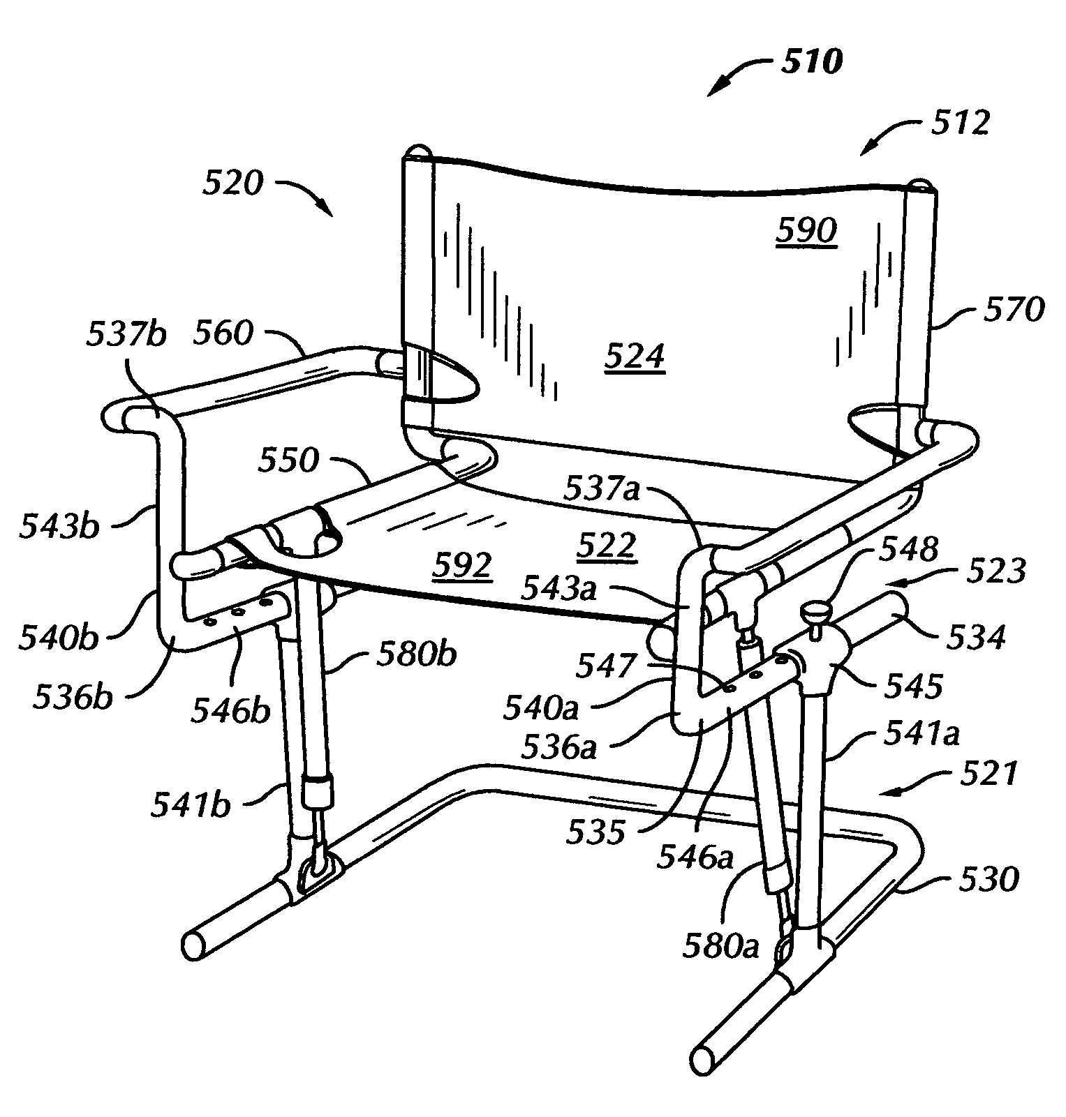
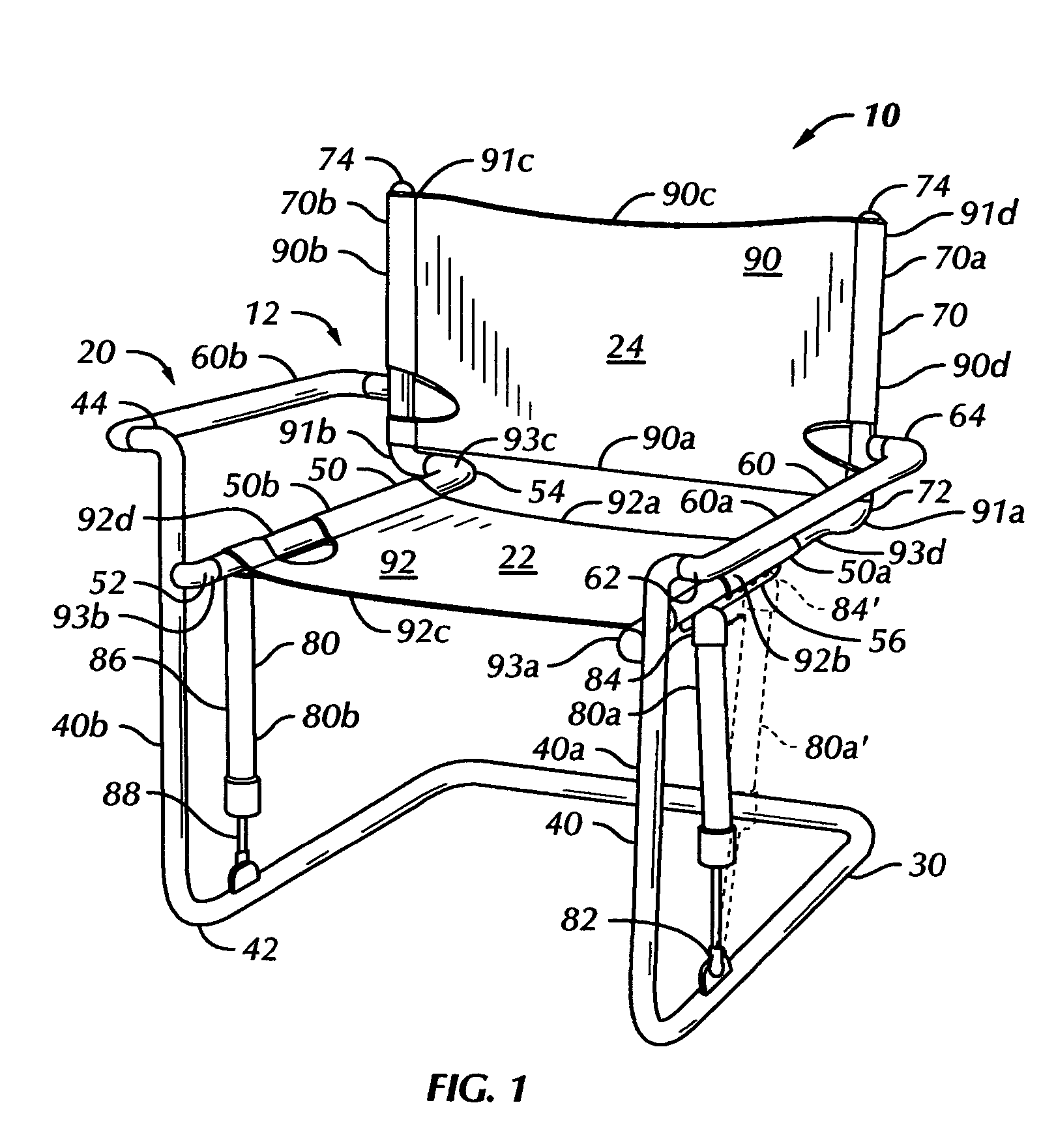
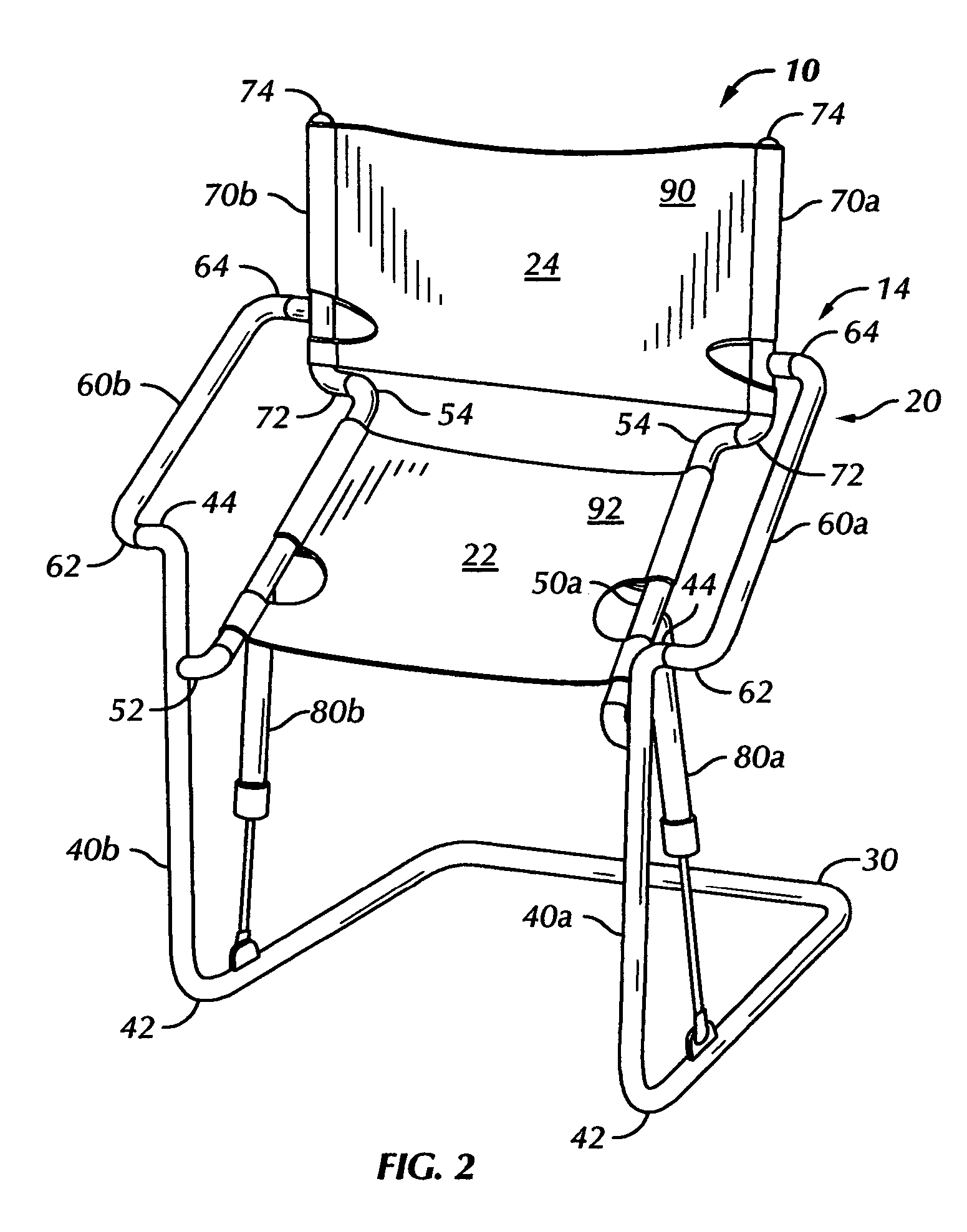
[0022]Referring to the figures, wherein like numerals are used to indicate like elements throughout, there are shown in FIGS. 1–7 multiple preferred embodiments of a lift chair in accordance with the present invention. With particular reference to FIGS. 1 and 2, a first preferred embodiment of a lift chair, generally designated 10, is illustrated. The lift chair 10 is movable between a seating position 12 (FIG. 1) and a rise-assist position 14 (FIG. 2). Major components of the lift chair 10 include a ...


PUM


Abstract

A chair is operable between a seating position and a rise-assist position. The chair comprises a base; first and second legs; a seat pivotally connected to the first and second legs; and a back pivotally connected to the seat. The chair further comprises first and second members pivotally connected at a first end to the legs, and pivotally connected at a second end to the back. At least portions of the legs, first and second members, back and seat form first and second four-bar linkages, respectively. At least one biasing member is pivotally connected at a first end to one of the base and at least one of the legs and pivotally connected at a second end to at least one of the four-bar linkages. The at least one biasing member operates to assist movement of the chair between the seating position and the rise-assist position.

Description

BACKGROUND OF THE INVENTION[0001]This invention relates to the art of chairs and, more particularly, to a lift chair for assisting a user when moving between seated and standing positions.[0002]Lift chairs are well known in the prior art. For example, U.S. Pat. No. 5,094,508 (Bathrick et al., hereinafter “Bathrick”) discloses an elevator chair used to assist a user seated in the chair when moving to a standing position. More specifically, Bathrick discloses a lift chair having a first seated position (FIG. 2), wherein a back is substantially vertical and a seat is substantially horizontal, and a second, lift position (FIG. 3), wherein the back remains substantially vertical and a rear portion of the seat pivots upwardly relative to a front portion of the seat to assist the user in standing. Bathrick employs two four-bar mechanisms formed by members 30, 54, 61 and 24 and 31, 55, 61 and 25, respectively. Members 30 and 31 are telescoping. A drive tube 42 moves the back frame assembly ...

Claims


Application Information

Patent Timeline
Patent Type & Authority Patents(United States)
IPC IPC(8): A61G15/00A47C1/02A47C1/029A47C9/00A61G5/14
CPCA61G5/14Y10S297/10
Inventor BRESSLER, PETER W.WEIMAN, ANDREW
Owner BRESSLER PETER
Why Eureka
Try Eureka