Quick connect coupling

a technology of quick connection and coupling, which is applied in the direction of couplings, adjustable joints, water supply installation, etc., can solve the disadvantage of large size of quick coupling, and achieve the effect of easy and safe coupling and releas

Active Publication Date: 2006-03-07
FASTER SPA
View PDF10 Cites 31 Cited by
  • Summary
  • Abstract
  • Description
  • Claims
  • Application Information

AI Technical Summary

Benefits of technology

[0009]Accordingly, the aim of the present invention is to provide a quick coupling the tubular element and a rod element of which can be easily and safely coupled and released under pressure, while omitting complex bleeding valves and achieving this object by a simple modification of the conventional components of the quick coupling, in particular of a push-pull type.

Problems solved by technology

However, as it should be apparent, the provision of a bleeding valve would allow a coupling or releasing operation to occur also when the quick coupling is subjected to hydraulic pressure; accordingly, in this case, the quick coupling would have a very complex construction including a plurality of mechanical elements to form said bleeding valve to be installed in the coupling body, which bleeding valve, moreover, will occupy a comparatively large space and, consequently, also the quick coupling will disadvantageously have a large size.

Method used


Image

  • Quick connect coupling
  • Quick connect coupling
  • Quick connect coupling

Examples


Embodiment Construction

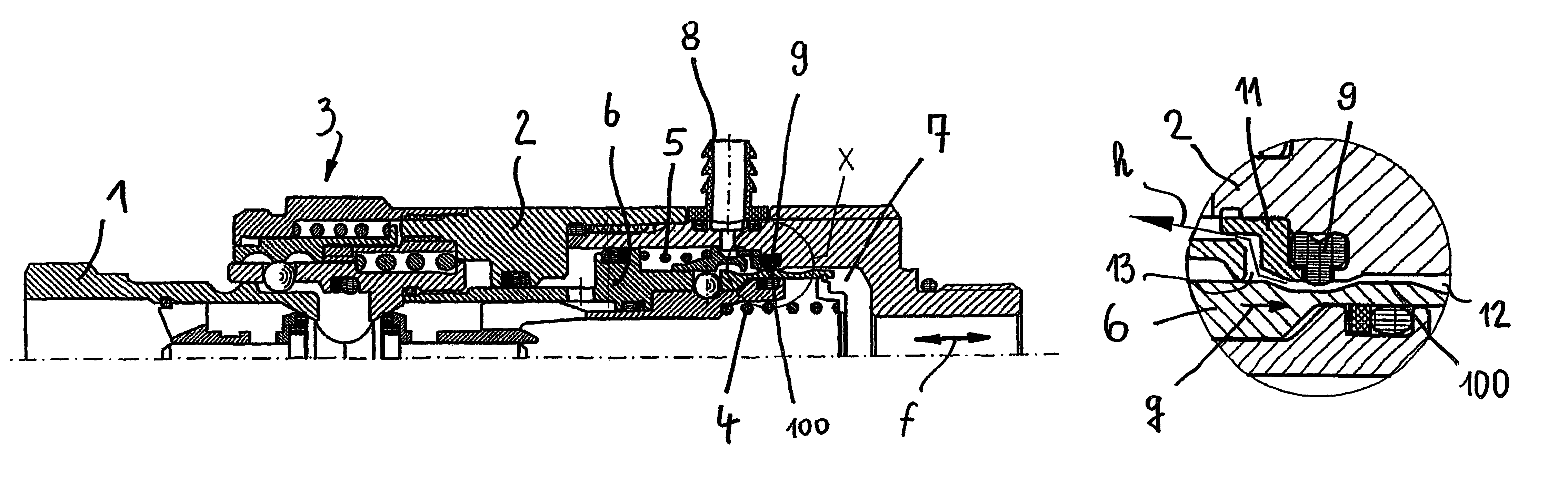
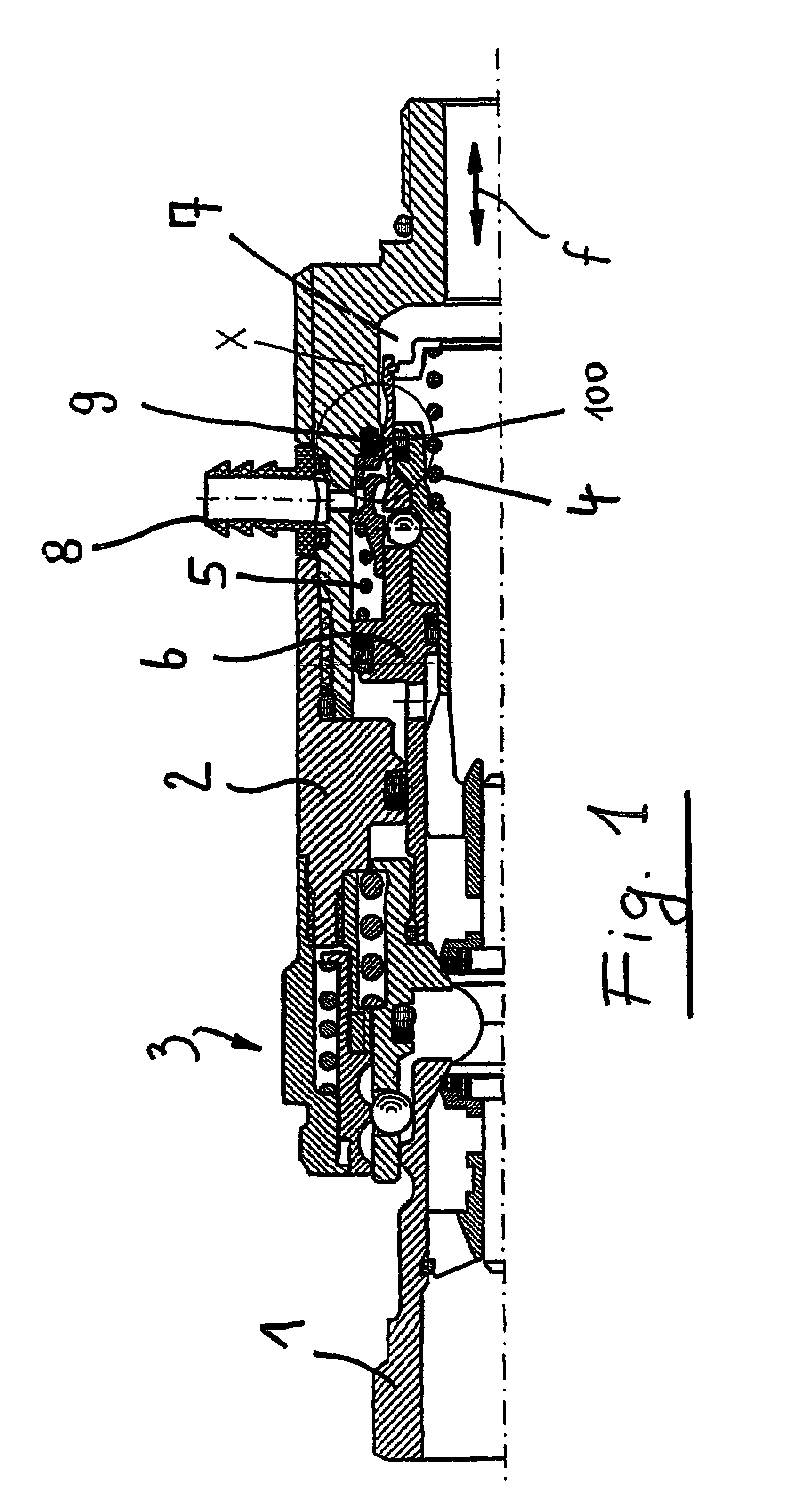
[0026]FIG. 1 shows a half of a rod-like element 1 as it is introduced into a tubular element 2 of a prior quick coupling, generally indicated by 3.

[0027]The hydraulic fluid is axially conveyed, under a high pressure, through the coupling 3, as schematically indicated by the arrow (f).

[0028]In said tubular element 2 a tubular body, generally indicated by 6 of a type known in the prior art and counterbiassed by urging springs 4 and 5 is slidably supported.

[0029]Because of the hydraulic fluid present herein, high pressures are generated in the zone 7 of the tubular element 2.

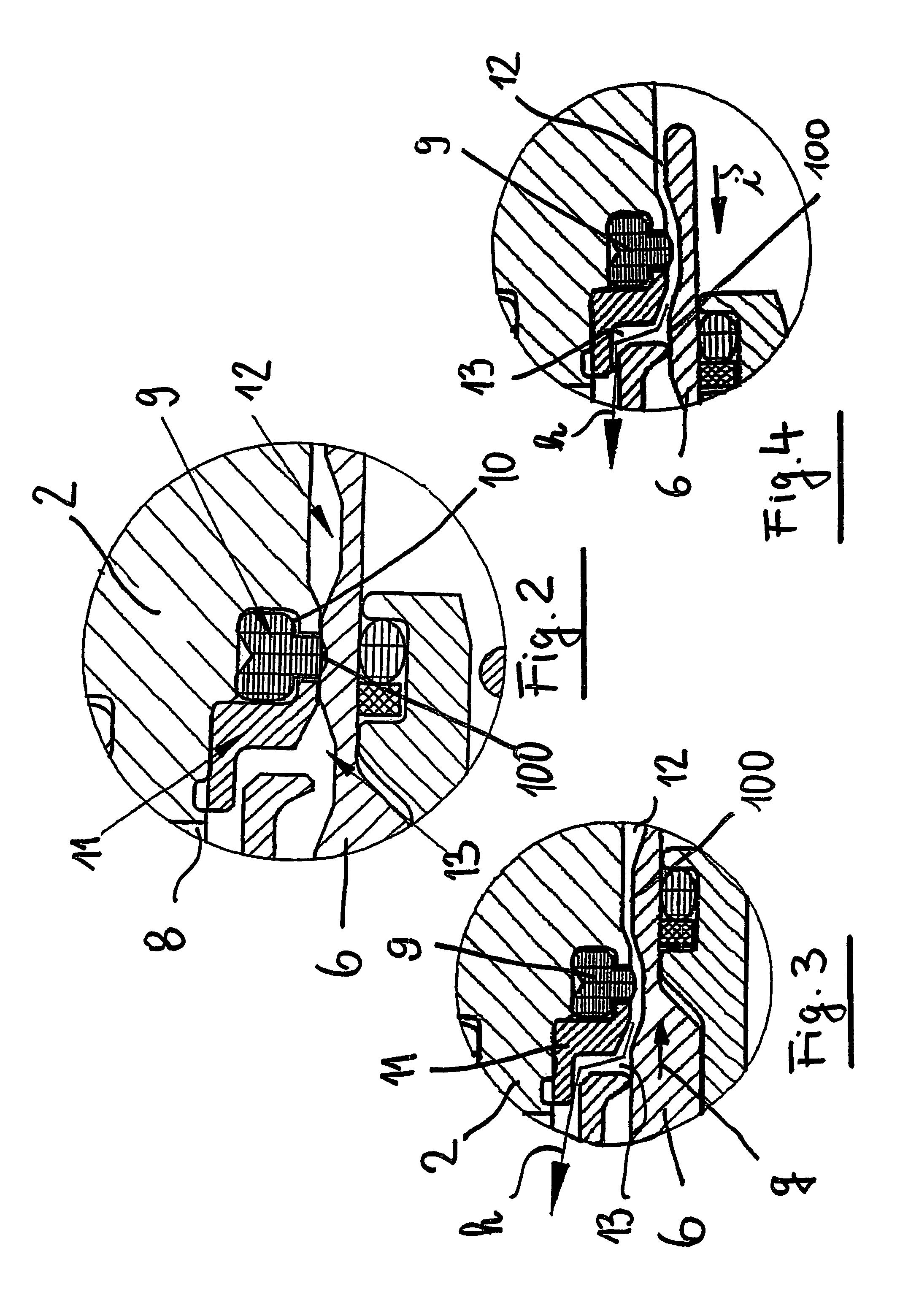
[0030]To prevent the hydraulic fluid from undesirably and uncontrollably exiting a conventional bleeding fitting 8, in this region an annular gasket 9 tightly bearing on the outer mantle 100 of the tubular element 6 is provided, said tubular element 6 being adapted to slide against an urging spring 200.

[0031]The gasket 9, as clearly shown in FIG. 2, is housed in a recess 10, formed on the inner circumference of the...


PUM


Abstract

An annular gasket is stationarily mounted on one coupler, and a tubular body is mounted for axial sliding movement within another coupler. The body has an outer wall formed with a sealing surface that sealingly engages the gasket in a sealed position, and with an outer channel that is spaced from the gasket in a bleed position in which pressurized fluid within the couplers is released to a bleed fitting.

Description

BACKGROUND OF THE INVENTION[0001]The present invention relates to a quick coupling with a connecting, respectively a releasing, capability in the presence of a pressurized hydraulic fluid.[0002]Quick couplings or fittings, in particular of a so-called “push-pull” type for coupling resilient pipes conveying a pressurized fluid are already commercially available.[0003]Said fittings comprise a tubular element and a rod like-element, which can be coupled to one another under a pushing force, or can be disengaged from one another by applying on the fitting elements a pulling force.[0004]In a particular advantageous manner, the above mentioned connecting and releasing operations can be also carried out as pressurized fluid are present in the pipes and in the quick coupling constructional elements.[0005]To perform the mentioned connecting and releasing operations as a high pressure is present in said pipes or hydraulic devices, the coupling tubular element comprises in inner bleeding means...

Claims


Application Information

Patent Timeline
Patent Type & Authority Patents(United States)
IPC IPC(8): F16L37/18F16L37/32F16L37/62
CPCF16L37/32F16L37/62Y10S285/924Y10T137/87965
Inventor AROSIO, MASSIMO
Owner FASTER SPA
Why Eureka
Try Eureka