Mask cushion and frame assembly

a technology which is applied in the field of mask cushion and frame assembly, can solve the problems of increasing manufacturing cost, the inability to easily remove the mask for separate cleaning from the frame,

Inactive Publication Date: 2006-04-04
RESMED LTD
View PDF107 Cites 121 Cited by
  • Summary
  • Abstract
  • Description
  • Claims
  • Application Information

AI Technical Summary

Benefits of technology

[0010]Preferably, the clip's securing means includes at least one securing tab which engages a respective recess in the mask frame, and more preferably on a lateral flange of rim portion of the frame.

Problems solved by technology

A disadvantage with this approach is that the cushion cannot easily be removed for separate cleaning from the frame.
Furthermore, there is an increased manufacturing cost since gluing requires assembly time and adhesive.

Method used


Image

  • Mask cushion and frame assembly
  • Mask cushion and frame assembly
  • Mask cushion and frame assembly

Examples


Embodiment Construction

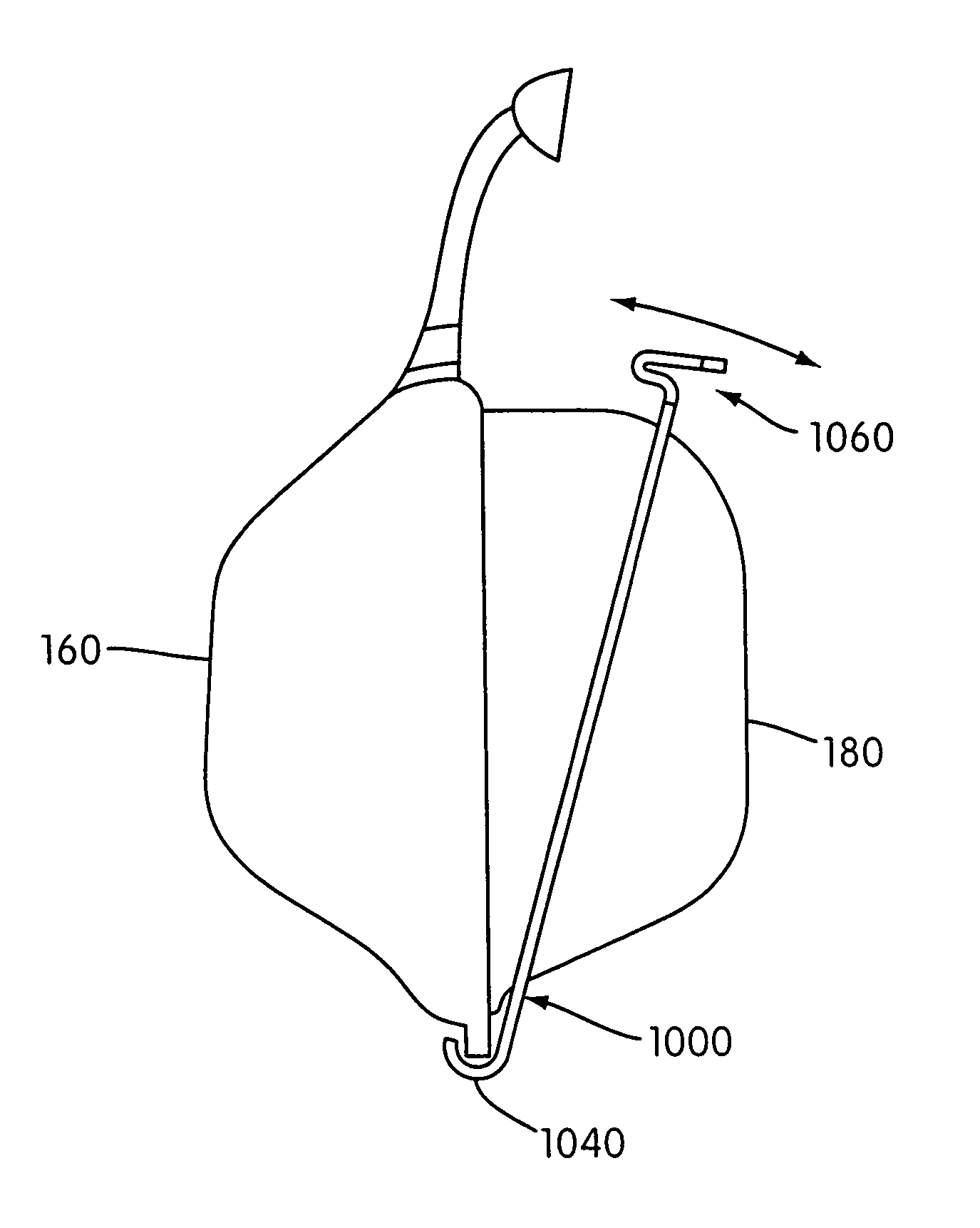
[0058]The method and apparatus for securing a cushion to a mask frame includes a combination of tongue and groove mechanism and a clip in the form of a collar member which passes over and engages both the cushion and the frame.

[0059]A nasal mask fame including a rim portion according to an embodiment of the invention is shown in FIG. 5a and FIG. 5b. The frame (160) is constructed as a substantially rigid shell of polycarbonate or similar transparent plastics material, and incorporates a gas inlet aperture (610) for connection to a gas delivery conduit (not shown) of a patient gas delivery system.

[0060]The frame (160) is generally triangular in front view, covering the patient's nose, and defines a cavity which is open at its rear, the rear opening being surrounded by a rim portion (600) which follows a locus approximating the contours of a patient's face.

[0061]On the front surface of the frame, are strap connection points (630) for connection of the mask to patient headgear. Connect...


PUM

PropertyMeasurementUnit
widthaaaaaaaaaa
widthaaaaaaaaaa
heightaaaaaaaaaa

Abstract

A respiratory mask assembly includes a rigid mask frame with a rim portion including a rearwardly projecting tongue and lateral flange and a cushion having a rim with a corresponding groove and a rearwardly facing shoulder. A clip in the form of a collar passes over the cushion, engaging behind the shoulder, and has securing tabs that engage recesses in the flange.

Description

CROSS REFERENCE TO RELATED APPLICATIONS[0001]This application is a Divisional of U.S. application Ser. No. 10 / 123,484, filed Apr. 17, 2002, now now U.S. Pat. No. 6,796,308, which is a Continuation of U.S. application Ser. No. 09 / 501,004, filed Feb. 9, 2000, now U.S. Pat. No. 6,412,487, which is a Continuation-in-Part (CIP) of U.S. application Ser. No. 09 / 498,705, filed Feb. 7, 2000, now U.S. Pat. No. 6,491,034, a CIP of U.S. application Ser. No. 09 / 316,227, filed May 21, 1999, now U.S. Pat. No. 6,513,526; a CIP of U.S. Design application Ser. No. 29 / 101,860, filed Mar. 12, 1999, now U.S. Design Pat. No. D428,139; a CIP of U.S. Design application Ser. No. 29 / 101,861, filed Mar. 12, 1999, now U.S. Design Pat. No. D430,663; a CIP of U.S. Design application Ser. No. 29 / 101,862, filed Mar. 12, 1999, now U.S. Design Pat. No. D428,988; and a CIP of U.S. Design application Ser. No. 29 / 115,618, filed Dec. 16, 1999, now U.S. Design Pat. No. D443,355, each of which is incorporated by reference...

Claims


Application Information

Patent Timeline
Patent Type & Authority Patents(United States)
IPC IPC(8): A62B18/08A61M16/06A61M16/08A61M16/20A62B18/02
CPCA61M16/0616A61M16/06A61M16/08A61M16/0633A61M16/0683A61M16/0638A61M16/0057A61M16/0666Y10T29/49863A61M16/208A61M2210/0618A61M16/0622A61M16/065
Inventor GUNARATNAM, MICHAEL K.SMART, GREGORY S.KWOK, PHILIP R.
Owner RESMED LTD
Why Eureka
Try Eureka