Projection display systems utilizing light emitting diodes and light recycling

a technology of light-emitting diodes and projection display systems, which is applied in incadescent envelopes/vessels, lighting and heating apparatuses, instruments, etc., can solve the problems of low reflectivity of devices, the inability to produce optical output images whose luminance is higher, and the current use of leds for projection display systems. achieve the effect of increasing the effective brightness of the first light source, increasing the effective brightness of the second light source, and increasing the effective brightness of the third light sour

Inactive Publication Date: 2006-04-11
GOLDENEYE
View PDF7 Cites 151 Cited by
  • Summary
  • Abstract
  • Description
  • Claims
  • Application Information

AI Technical Summary

Problems solved by technology

Light sources such as LEDs are currently not used for projection display systems because LED sources do not have sufficient output brightness.
In a conventional optical system that transports light from an input source at one location to an output image at a second location, one cannot produce an optical output image whose luminance is higher than the luminance of the light source.
However, under certain conditions utilizing such light recycling, the effective luminance of the source as well as the maximum exiting luminance of the optical system can be higher than the intrinsic luminance of the source in the absence of recycling, a result that is not predicted by the standard etendue equations.
Typical prior LED designs placed one electrode on top of the device, which interfered with the light output from the top surface and resulted in devices with low reflectivity.
However, even the new green, cyan, blue and ultraviolet gallium nitride, indium gallium nitride, aluminum gallium nitride and aluminum nitride LEDs do not have sufficient luminance for many applications.
Coherent semiconductor laser light sources typically have higher brightness than incoherent light sources, but semiconductor laser light sources are not suitable for many applications such as displays due to the formation of undesirable speckle light patterns that result from the coherent nature of the light.
However, such systems do not reproduce all the colors that a human eye can visualize.

Method used


Image

  • Projection display systems utilizing light emitting diodes and light recycling
  • Projection display systems utilizing light emitting diodes and light recycling
  • Projection display systems utilizing light emitting diodes and light recycling

Examples


Embodiment Construction

[0047]The preferred embodiments of the present invention will be better understood by those skilled in the art by reference to the above figures. The preferred embodiments of this invention illustrated in the figures are not intended to be exhaustive or to limit the invention to the precise form disclosed. The figures are chosen to describe or to best explain the principles of the invention and its applicable and practical use to thereby enable others skilled in the art to best utilize the invention.

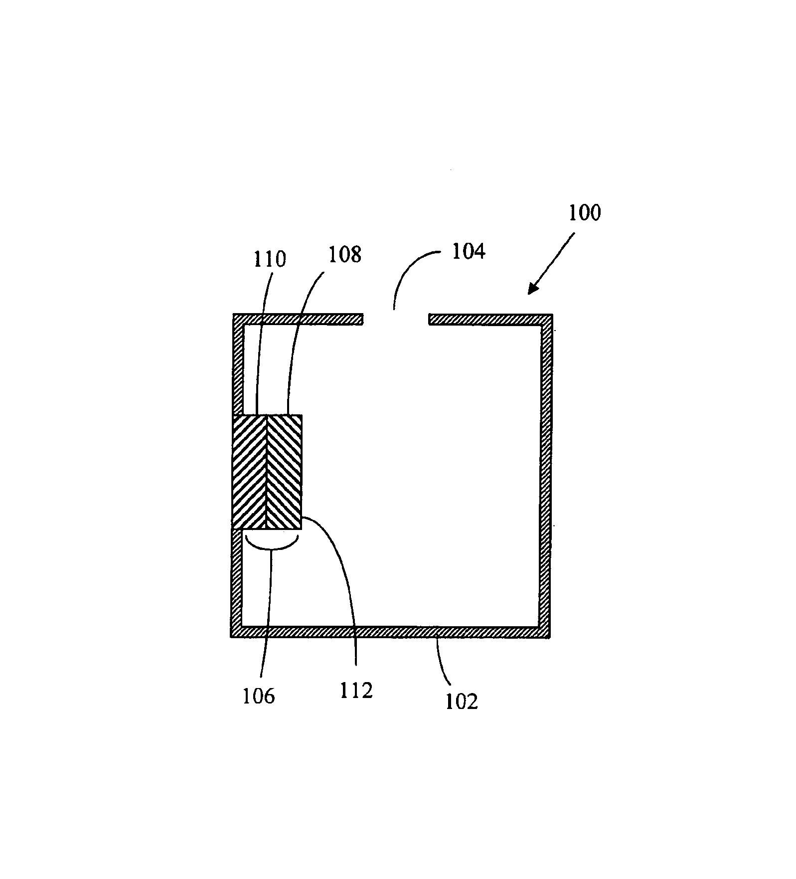
[0048]The embodiments of this invention are comprised of at least one illumination system and at least one imaging light modulator. The illumination system is further comprised of a light source, a light-recycling envelope, a light output aperture located in the surface of the lightrecycling envelope and a light-collimating means.

[0049]The preferred light source of this invention comprises at least one light-emitting diode (LED). Preferred LEDs are inorganic light-emitting diodes and org...


PUM

PropertyMeasurementUnit
refractive indexaaaaaaaaaa
wavelength rangeaaaaaaaaaa

Abstract

A projection display system has at least one light-recycling illumination system and at least one imaging light modulator. The light-recycling illumination system includes a light source that is enclosed within a light-recycling envelope. The light source is a light-emitting diode that emits light, an a fraction of that light will exit the light-recycling envelope through an aperture. The light-recycling envelope recycles a portion of the light emitted by the light source back to the light source in order to enhance the luminance of the light exiting the aperture. The fraction of the light that exits the aperture is partially collimated and is directed to the imaging light modulator. The imaging light modulator spatially modulates the partially collimated light to form an image.

Description

CROSS REFERENCE TO RELATED APPLICATION[0001]This application is related to U.S. Patent Application Ser. No. 10445136 entitled “ILLUMINATION SYSTEMS UTILIZING HIGHLY REFLECTIVE LIGHT EMITTING DIODES AND LIGHT RECYCLING TO ENHANCE BRIGHTNESS,” which is herein incorporated by reference. This application is also related to U.S. Patent Application Ser. No. 10 / 814,043 entitled “ILLUMINATION SYSTEMS UTILIZING LIGHT EMITTING DIODES AND LIGHT RECYCLING TO ENHANCE OUTPUT RADIANCE” and to U.S. patent application Ser. No. 10 / 814,044 entitled “ILLUMINATION SYSTEMS UTILIZING MULTIPLE WAVELENGTH LIGHT RECYCLING,” both of which are filed concurrently with this application and which are herein incorporated by reference.TECHNICAL FIELD[0002]This invention relates to projection display systems incorporating light-emitting diodes (LEDs).BACKGROUND OF THE INVENTION[0003]Illumination systems are used as either stand-alone light sources or as internal light sources for more complex optical systems. Exampl...

Claims


Application Information

Patent Timeline
Patent Type & Authority Patents(United States)
IPC IPC(8): G03B21/00F21V7/00G03B21/20G03B21/26G03B21/28
CPCG03B21/28
Inventor BEESON, KARL W.ZIMMERMAN, SCOTT M.
Owner GOLDENEYE
Why Eureka
Try Eureka