
Shower surround structure

a shower and structure technology, applied in the field of shower surround structure, can solve problems such as uncomplicated assembly

Active Publication Date: 2006-04-18
DELTA FAUCET COMPANY
View PDF4 Cites 43 Cited by
  • Summary
  • Abstract
  • Description
  • Claims
  • Application Information

AI Technical Summary

Benefits of technology

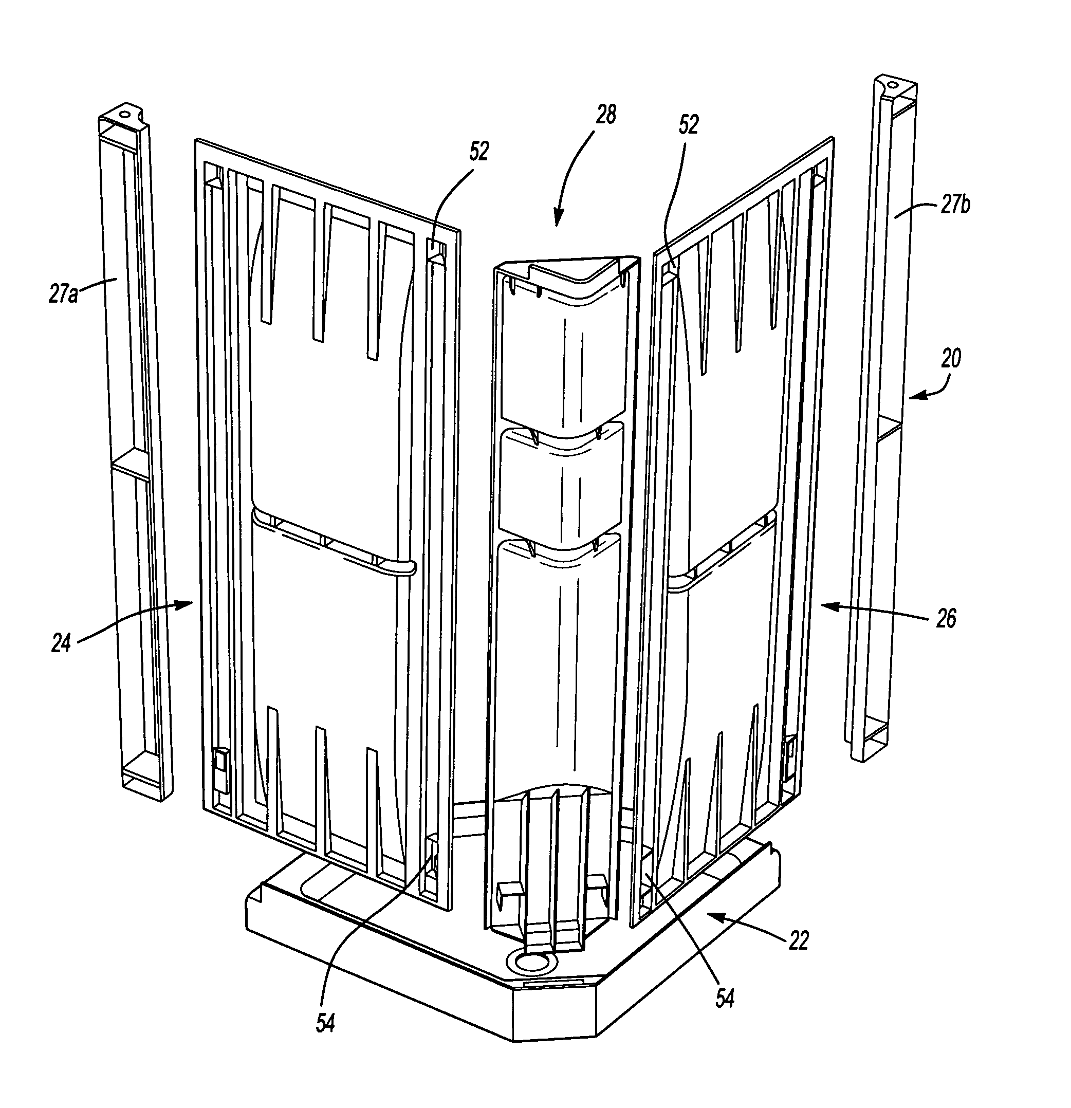
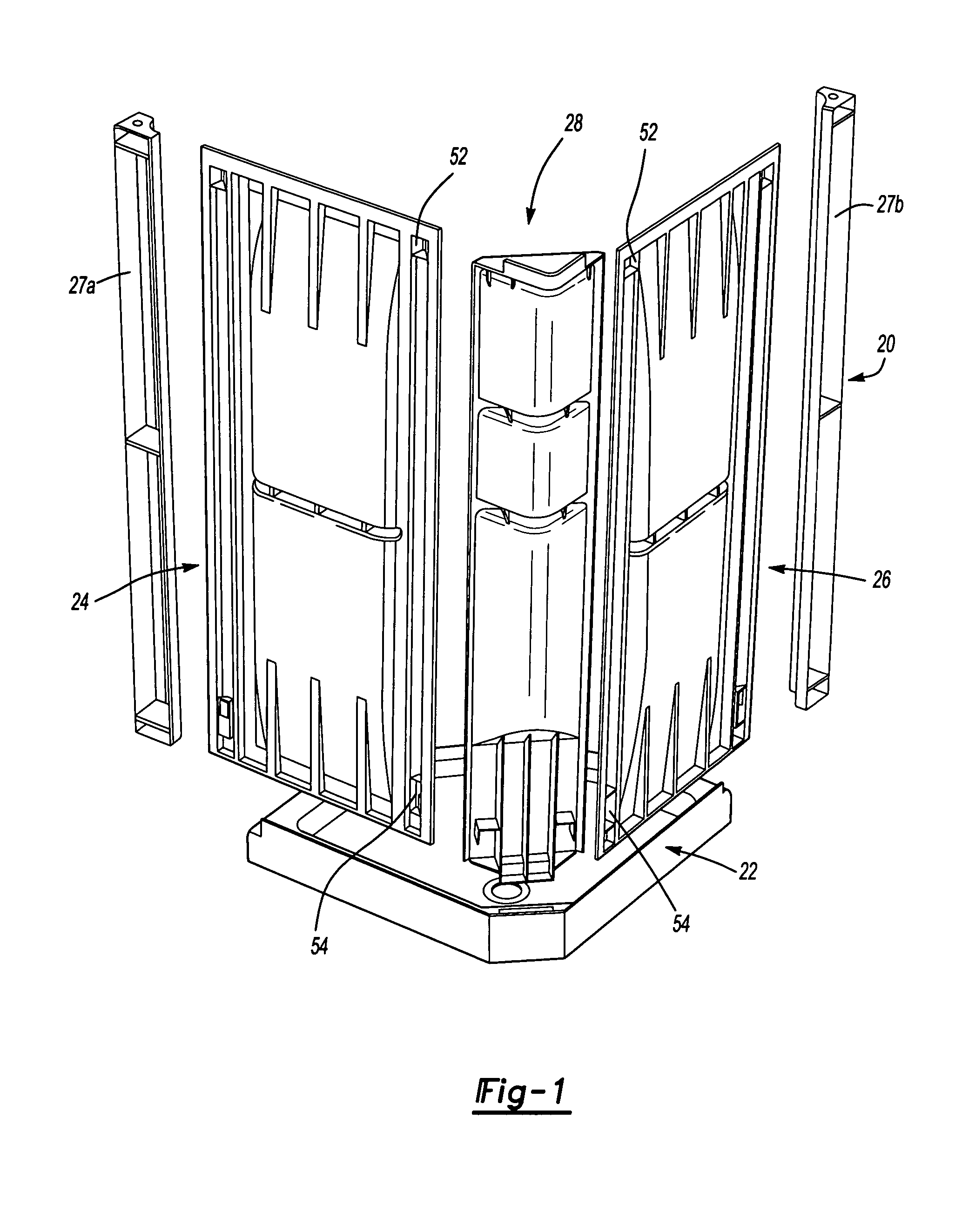
[0006]The corner portion includes an upper lock tab and a lower lock tab adjacent the outer edges. An upper lock slot and a lower lock slot are located adjacent the inner edge of each wall portion which engage the corner portion. Each side of the corner portion includes a corner flange arranged substantially perpendicular to a corner planar surface. Each of the corner planar surfaces are substantially parallel to the wall portions when in a mounted position. The corner flange is received within a molded slot which extends along the vertical length of the wall portion to provide an aesthetically pleasing interface. The corner flange and the molded slots when combined with the upper lock tab and the lower lock tab, which respectively engage the upper lock slot and the lower lock slot, provide a watertight interlocking arrangement between the corner portion and the wall portions.

Problems solved by technology

One problem which arises with products of this type is that of an uncomplicated assembly which will form a suitable joint between the surround portions.

Method used


Image

  • Shower surround structure
  • Shower surround structure
  • Shower surround structure

Examples


Embodiment Construction

[0022]FIG. 1 illustrates a general exploded view of a molded shower surround 20 which is formed of four pieces of molded plastic. A base portion 22 receives wall portions 24 and 26, a corner portion 28 therebetween, and an edge trim portion 27a, 27b. It should be understood that any number of wall portions will benefit from the present invention and that although a particular component arrangement is disclosed in the illustrated embodiment, other arrangements will benefit from the instant invention.

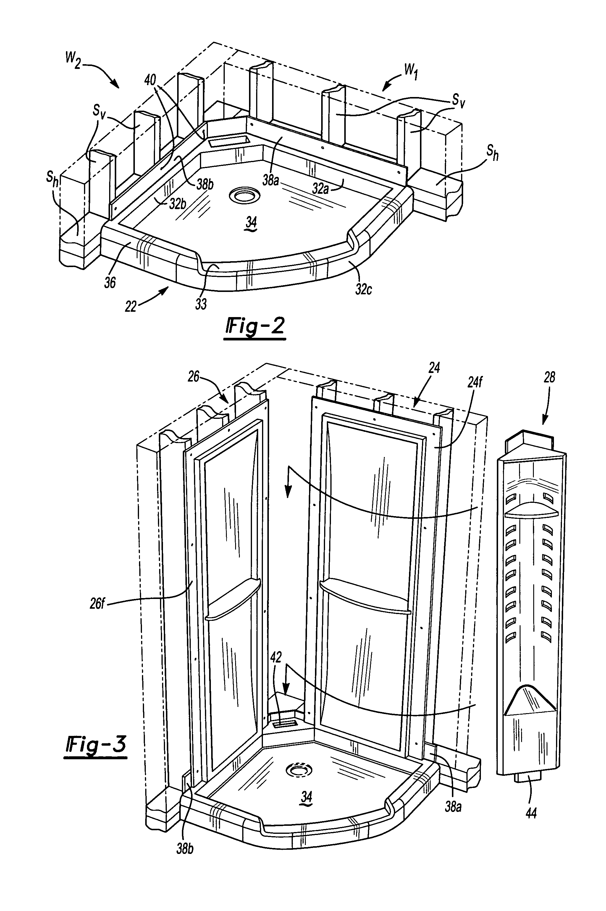
[0023]Referring to FIG. 2, the base portion is preferably located in a corner between two walls W1 and W2 which typically include a multiple of vertical wooden studs Sv and horizontal studs Sh. The base portion 22 fits adjacent the horizontal studs Sh. It should be understood that the wooden studs Sv, Sh are typically two-by-fours or the like usual for wall framing.

[0024]The base portion 22 defines a floor 34 bounded by a raised ledge 36. The ledge 36 of the base portion 22 preferably inc...


PUM


Abstract

A molded shower surround includes a base portion which receives wall portions and a corner portion therebetween. The corner portion includes an upper lock tab and a lower lock tab adjacent an outer edge. An upper lock slot and a lower lock slot are located adjacent the inner edge of each wall portions which engage the corner portion. Each side of the corner portion includes a corner flange arranged substantially perpendicular to a corner planar surface. The corner flange and the molded slots when combined with the upper lock tab and the lower lock tab which respectively engage the upper lock slot and the lower lock slot, provide a watertight interlocking arrangement between the corner portion and the wall portions. In one assembly method, the corner portion and a wall portion are locked into a sub-assembly then this sub-assembly is lifted and slide onto to a second wall which may already be mounted to the base portion. In another assembly the corner and wall portion are assembled to the base portion such that the assembled shower assembly can be “slid” into a corner.

Description

BACKGROUND OF THE INVENTION[0001]The present invention relates to an interface between panels of a molded plastic shower surround and a method of assembly therefor.[0002]Conventional modular tub / shower units often include a base portion at the bottom and two or more wall portions. The whole structure is mounted adjacent a wall or corner to form a waterproof surround. The fully enclosed waterproof structure is highly advantageous in that it prevents the escape of water into the wall structure despite the shower spraying water onto the surrounding walls.[0003]One problem which arises with products of this type is that of an uncomplicated assembly which will form a suitable joint between the surround portions. Various styles of joint have been used, each of which provide particular tradeoffs in complexity, aesthetics, and sealing ability.[0004]Accordingly, it is desirable to provide a waterproof assembly interface between wall portions of a molded plastic shower surround which is uncom...

Claims


Application Information

Patent Timeline
Patent Type & Authority Patents(United States)
IPC IPC(8): A47K3/022A47K3/28A47K3/30
CPCA47K3/30A47K3/281
Inventor HELMETSIE, EUGENE A.ZARKER, JR., HARPER F.PRACEL, TOMASZ
Owner DELTA FAUCET COMPANY
Learn More