Swim lap counter/timer

a lap counter and timer technology, applied in the field of lap counters, can solve the problems of swimmers being interrupted, swimmers universally experiencing a problem of remembering how many laps, and swimmers not being able to access information

Inactive Publication Date: 2006-04-18
BAILEY BRAD
View PDF6 Cites 29 Cited by
  • Summary
  • Abstract
  • Description
  • Claims
  • Application Information

AI Technical Summary

Problems solved by technology

Lap swimmers universally experience a problem remembering how many laps they have swum, especially while in the process of completing longer sets.
Also representing a problem to swimmers, is the ability to ascertain the running time of a swim effort while performing the specific technicalities of a swim stroke, as well as obtaining split-times for individual laps in a set, or accurate total completion times. Aside from depending on assistance from another person, devices are available for swimmers to record such times themselves; however, those require swimmers to interrupt very technical swim-stroke maneuvers to press tiny buttons.
Even then, this information is not available to the swimmer while performing a set without pausing or severely interrupting stroke mechanics to look at a wrist or finger-mounted recording device.
This system is not suitable for practice and does not provide immediate feedback to the swimmer.
The problem with using a bendable bracket is that it ultimately fails due to metal fatigue when trying to bend the bracket to accommodate different pool configurations.
Furthermore, the position of the counter display above the water requires that the swimmer lift his or her head out of the water to view the display, which interrupts the swimmer's movements.
Use of this unit would interfere with a swimmer's movements and the display is not visible to the swimmer while he or she is swimming.
The unit cannot accommodate a significant pool deck overhang and the display above the water surface is inconvenient for the swimmer.
It is not suitable for, or readily adapted to, other pool configurations.

Method used


Image

  • Swim lap counter/timer
  • Swim lap counter/timer
  • Swim lap counter/timer

Examples


Embodiment Construction

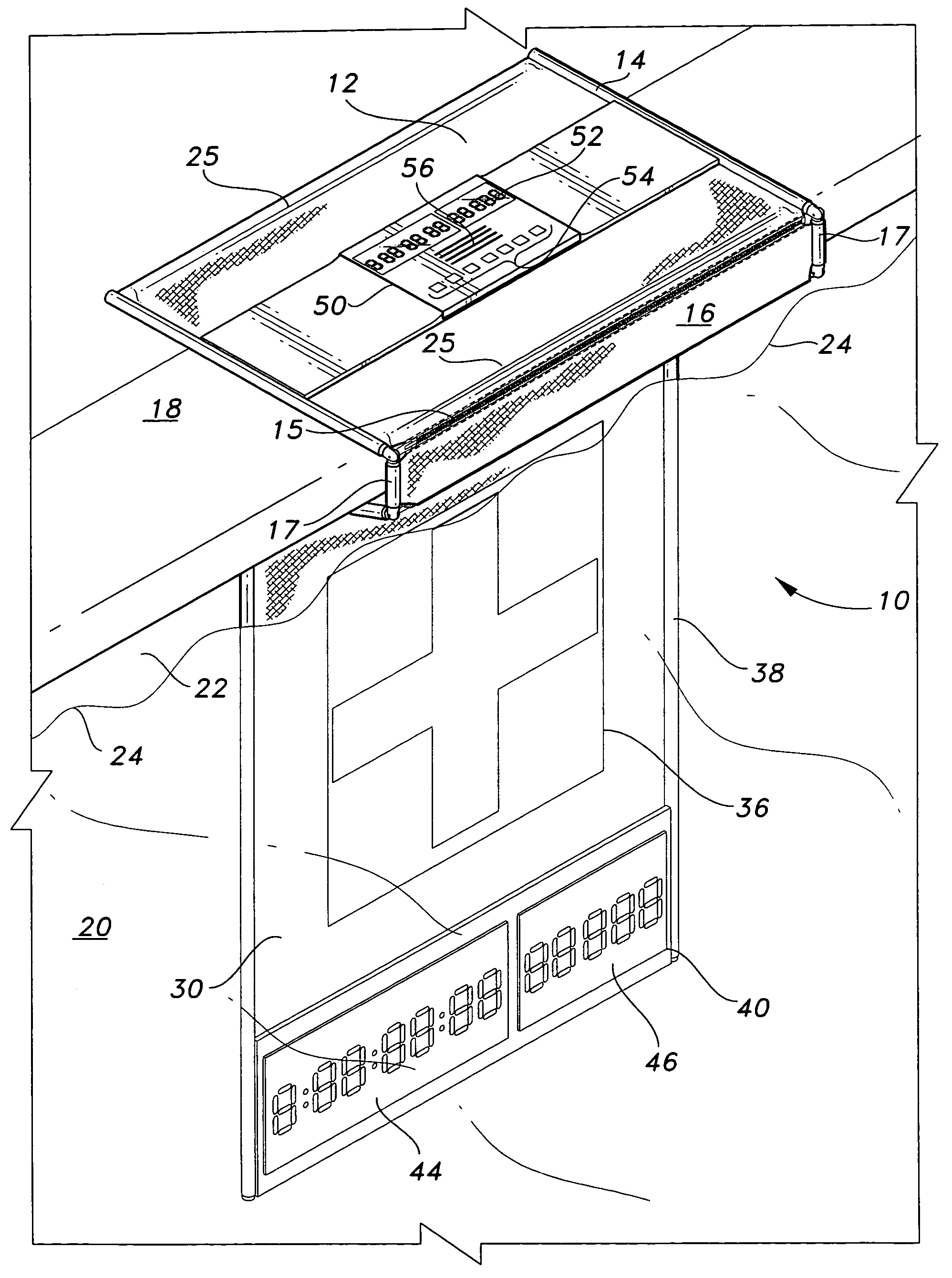
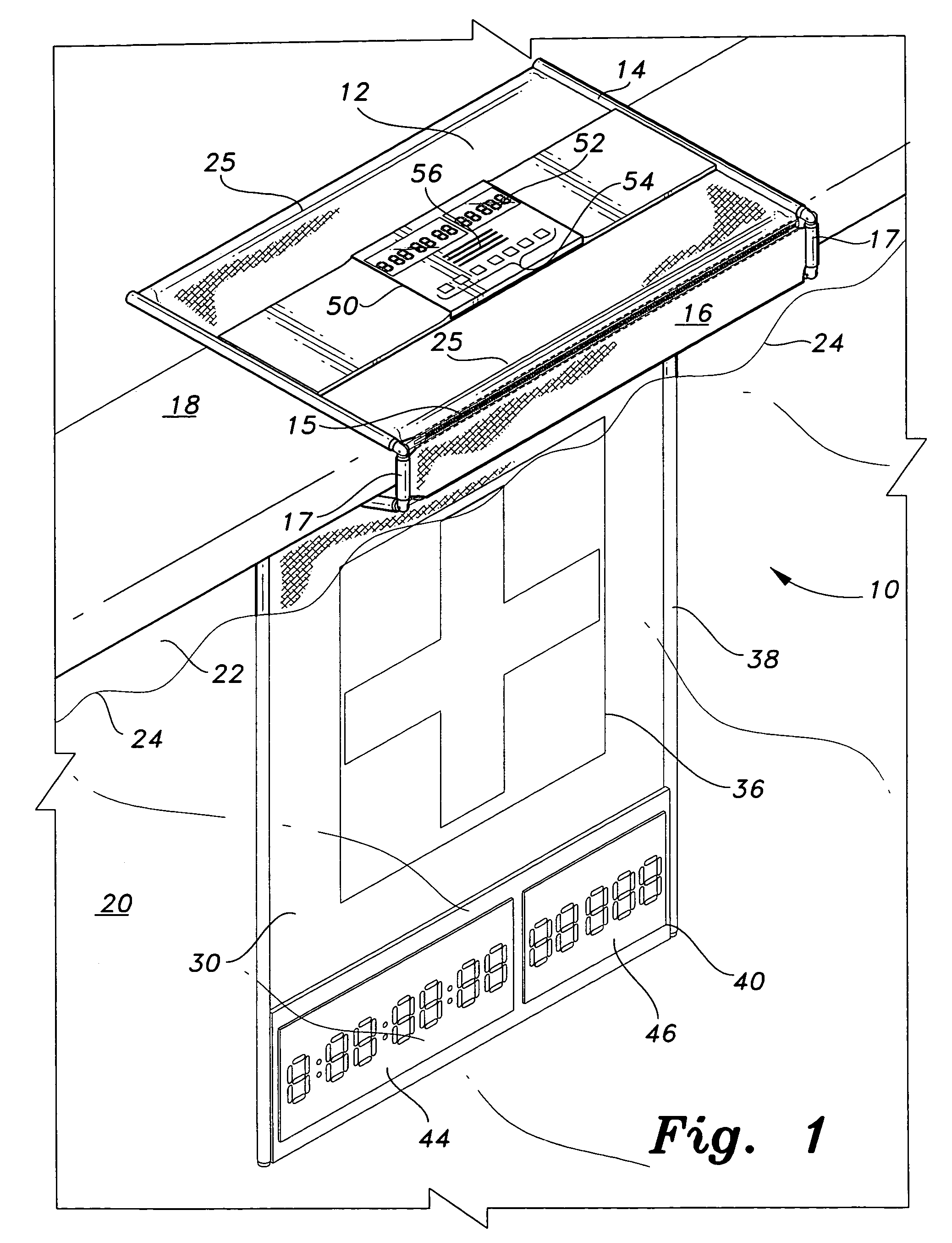
[0024]A swim lap counter-timer is shown generally at 10 in FIG. 1. This device has structural aspects, electronic aspects, and functional aspects. Each will be described in sequence below.

Structure

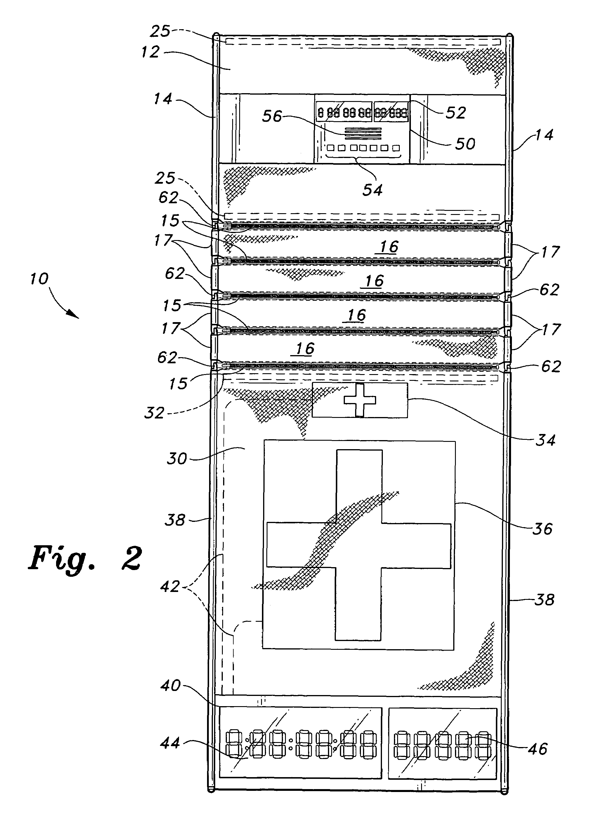
[0025]FIG. 1 shows an exemplary swim lap counter-timer including a top section 12 having an electronic control unit 50 and a bottom section 30 having at least one pressure sensitive panel and a digital display 40. Each section comprises a flexible mat. As will be further described below, top section 12 and bottom section 30 may be connected directly together, or one or more intermediate spacer sections 16 may be connected between top section 12 and bottom section 30 for the purpose of adapting swim lap counter-timer 10 to a specific swimming pool configuration. Each connection is connected to adjacent sections with a zipper joint 15. Other methods of connecting sections, including snaps, hooks, buttons, or hook-and-loop fasteners, such as that sold under the trademark “Velcro”, are contemp...


PUM


Abstract

The swim lap counter comprises a top section and a bottom section. In one aspect of the invention, the bottom section is suspended from the top section and comprises a pressure sensitive panel and a submersible digital display. The submersible digital display is disposed proximate the bottom edge of the bottom section.

Description

BACKGROUND OF THE INVENTION[0001]1. Field of the Invention[0002]The present invention relates to swim lap counter-timers for swimmers and, more specifically, to a portable electronic lap counter and timer of the type having a touch panel for sensing swimmer arrival time.[0003]2. Description of the Related Art[0004]Lap swimmers universally experience a problem remembering how many laps they have swum, especially while in the process of completing longer sets. Also representing a problem to swimmers, is the ability to ascertain the running time of a swim effort while performing the specific technicalities of a swim stroke, as well as obtaining split-times for individual laps in a set, or accurate total completion times. Aside from depending on assistance from another person, devices are available for swimmers to record such times themselves; however, those require swimmers to interrupt very technical swim-stroke maneuvers to press tiny buttons. Even then, this information is not avail...

Claims


Application Information

Patent Timeline
Patent Type & Authority Patents(United States)
IPC IPC(8): G04B37/00A63B31/08A63B69/12A63B71/06G04F8/00G04F10/00
CPCA63B69/12G04F10/00A63B71/0605
Inventor BAILEY, BRAD
Owner BAILEY BRAD
Why Eureka
Try Eureka