Switch contact

Inactive Publication Date: 2006-04-18
FLEXTRONICS AUTOMOTIVE
View PDF7 Cites 24 Cited by
  • Summary
  • Abstract
  • Description
  • Claims
  • Application Information

AI Technical Summary

Benefits of technology

[0024]The present invention advances the art and overcomes the above-identified shortcomings with push butt

Problems solved by technology

However, as described further below, the clearance frequently does not achieve the desired objective.
There are problems with the above-described general structure of push button and other contact-type switches.
As known to person skilled in the arts pertaining to electrical switches, such interruptions as the examples INT1 and INT2 may cause problems, and may require “debouncers” and other known electronic means to eliminate.
The are many applications and requirements, though, for which a mechanism as shown by the '202 patent may be impractical or infeasible.
Further, it is foreseeable that manufacturing tolerances, and time-related factors such as wear of the bridge conductor, deterioration of the material constituting the lever, and debris could result in insufficient or intermittent contact between the bridge and the contacts.

Method used


Image

  • Switch contact
  • Switch contact
  • Switch contact

Examples


Embodiment Construction

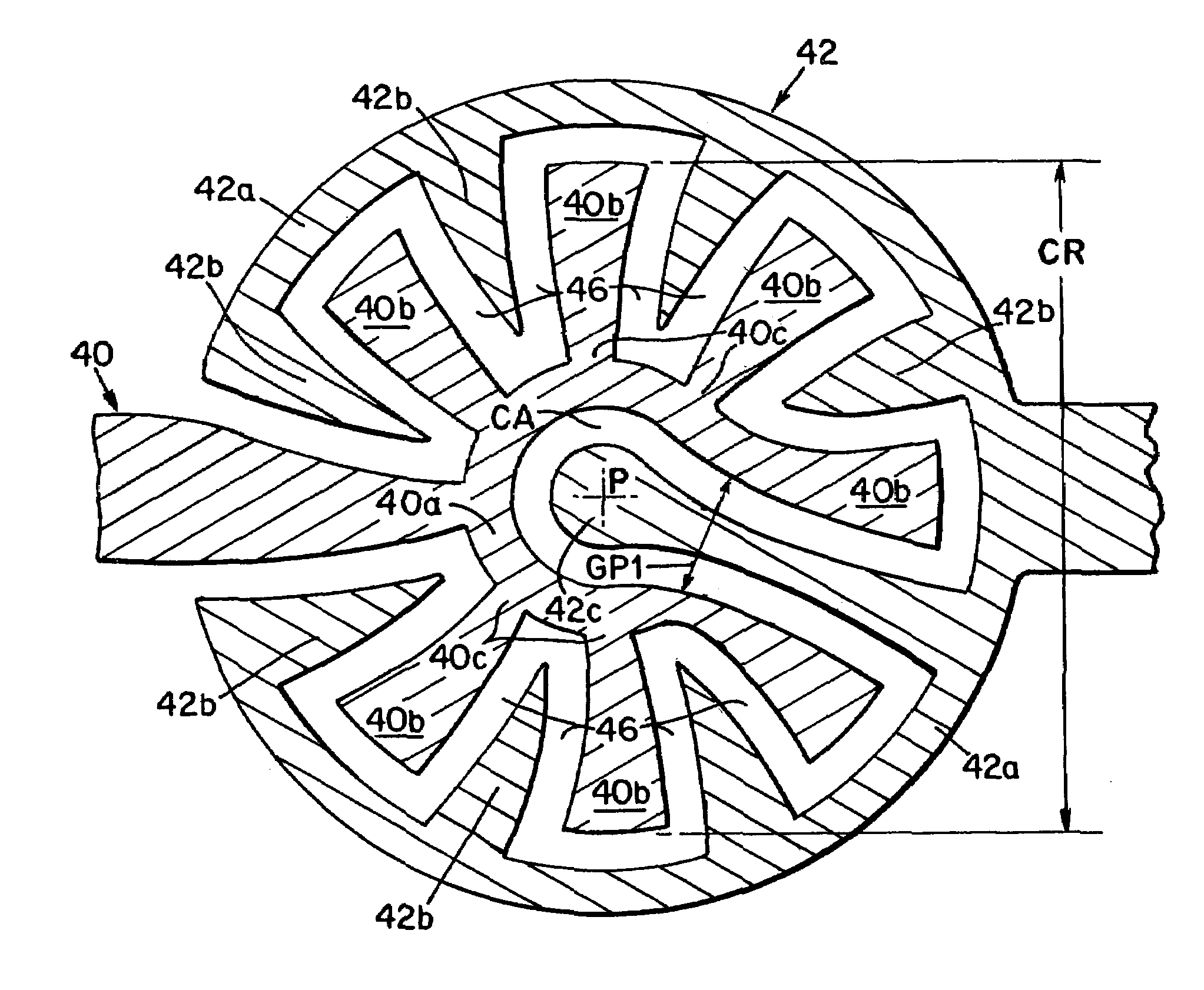
[0047]FIG. 9 shows a top elevation view of a first example embodiment of this invention. The FIG. 9 example includes an outward radial conductor 40 and an inward radial conductor 42, each disposed on an insulating substrate, not shown, substantially co-located with each other but aligned such that they do not have electrical contact. The FIG. 9 example of outward radial conductor 40 includes an inner circumferential conductor 40a extending around a center point P, to partially enclose a center area CA, and a plurality of radially extending fingers 40b, each extending outward from the conductor portion 40a. Preferably, the respective bases 40c of the outward radially extending fingers 40b are substantially evenly spaced from one another along the conductor 40a. In the depicted example, one of the radially extending fingers, labeled 40b′, extends to connect to a first switch terminal 46. The remaining radially extending fingers 40b extend to terminate at respective locations along a r...


PUM


Abstract

A conducting contact pair for a switch has a first conducting contact formed by a plurality of outward extending radial fingers arranged on a substrate, and a second conducting contact formed by a plurality of inward extending radial fingers. The first conducting contact and the second conducting contact are arranged with each inward extending radial finger extending between a corresponding pair of adjacent outward extending radial fingers. A bridge conductor is selectively pressed against the first conducting contact and the second contact to bridge any of the inward extending fingers to either of pair of adjacent outward extending radial fingers that it extends between.

Description

FIELD OF THE INVENTION[0001]This invention relates generally to an electrical switch contacts and, more particularly, to a pattern of electrical contacts arranged on a substrate in association with a movable bridge contact.DESCRIPTION OF THE RELATED ART[0002]Plunger-activated electrical switches, commonly referred to as “push button” switches, are used in association with, and are mounted on and in, a wide variety of consumer appliances, vehicles, medical equipment, military and industrial equipment. The function of a push button switch is, generally, to open and close an electrical path between at least one-input terminal of the switch and at least one output terminal of the switch. Typically the electrical path permits the flow of an electrical current, thereby energizing, or activating or deactivating a feature of, or changing a mode of operation of an electrical apparatus. There are many known structures for push button switches. A typical structure includes a first conducting c...

Claims


Application Information

Patent Timeline
IPC IPC(8): H01H1/06
CPCH01H13/79H01H2203/054H01H2203/02
Inventor SNEEK, BRIANWARREN, GARYCHAMUCZYNSKI, SIMONGRILLS, REGINALD
Owner FLEXTRONICS AUTOMOTIVE
Why Eureka
Try Eureka