Mounting apparatus for PCB

a technology for mounting apparatuses and pcbs, which is applied in the direction of casings/cabinets/drawers, instruments, casings/cabinets/drawers, etc., can solve the problems of motherboard damage, laborious and time-consuming tightening or removing fasteners, etc., and achieve the effect of quick and easy attachment and removal of a pcb

Inactive Publication Date: 2006-04-25
HON HAI PRECISION IND CO LTD
View PDF9 Cites 95 Cited by
  • Summary
  • Abstract
  • Description
  • Claims
  • Application Information

AI Technical Summary

Benefits of technology

[0007]Accordingly, an object of the present invention is to provide a mounting apparatus which allows quickly and readily attachment and removal of a PCB to and from a chassis of an electronic device.

Problems solved by technology

When installing or removing the motherboard, tightening or removing the fasteners is laborious and time-consuming.
Moreover, the motherboard is prone to be damaged if the tool slips during manipulation.

Method used


Image

  • Mounting apparatus for PCB
  • Mounting apparatus for PCB
  • Mounting apparatus for PCB

Examples


Embodiment Construction

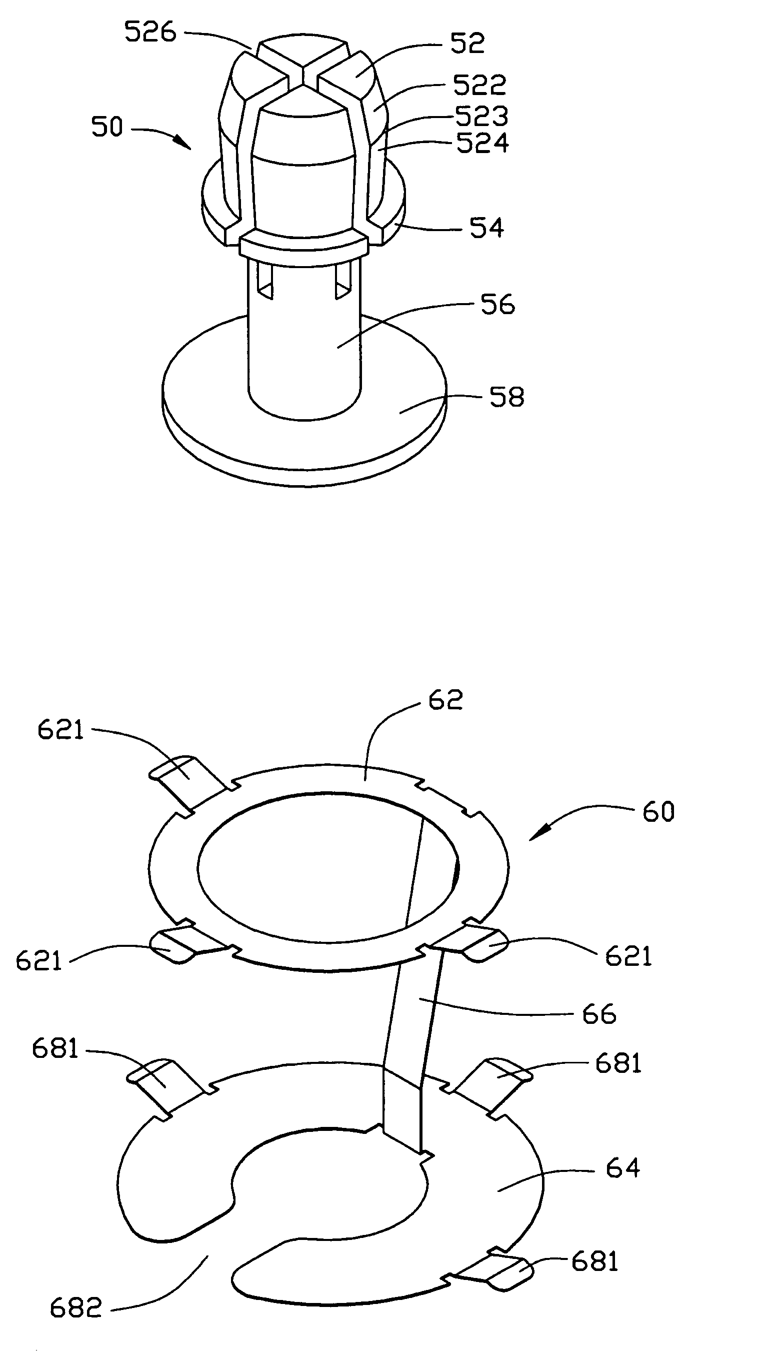
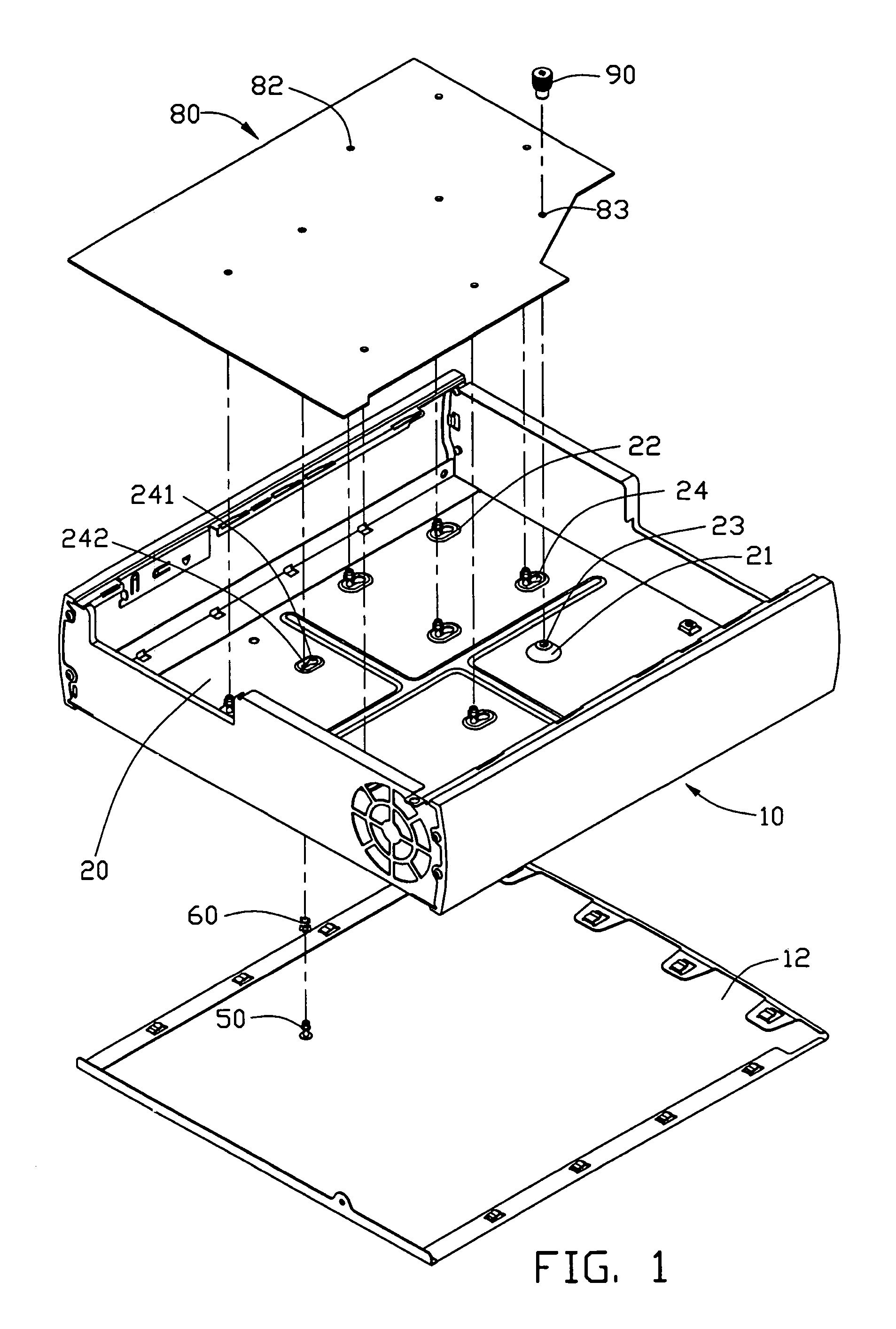
[0016]Referring to FIG. 1, a mounting apparatus in accordance with the preferred embodiment of the present invention is used for securing a PCB 80 in an electronic chassis 10. The PCB 80 defines a plurality of fixing apertures 82 and a through aperture 83 therein. The chassis 10 comprises a bottom panel 12. The mounting apparatus comprises a supporting plate 20, a plurality of standoffs 50, a plurality of grounding members 60, and a thumb screw 90.

[0017]The supporting plate 20 is disposed in the chassis 10, for supporting the PCB 80 thereon. The supporting plate 20 comprises a bulge 21 and a plurality of raised platforms 22. A screw hole 23 is defined in the bulge 21, corresponding to the through aperture 83 to engage with the thumb screw 90. A through hole 24 is defined in each raised platform 22. The through hole 24 comprises a circular hole 241, and a slot 242 extending from the circle hole 241.

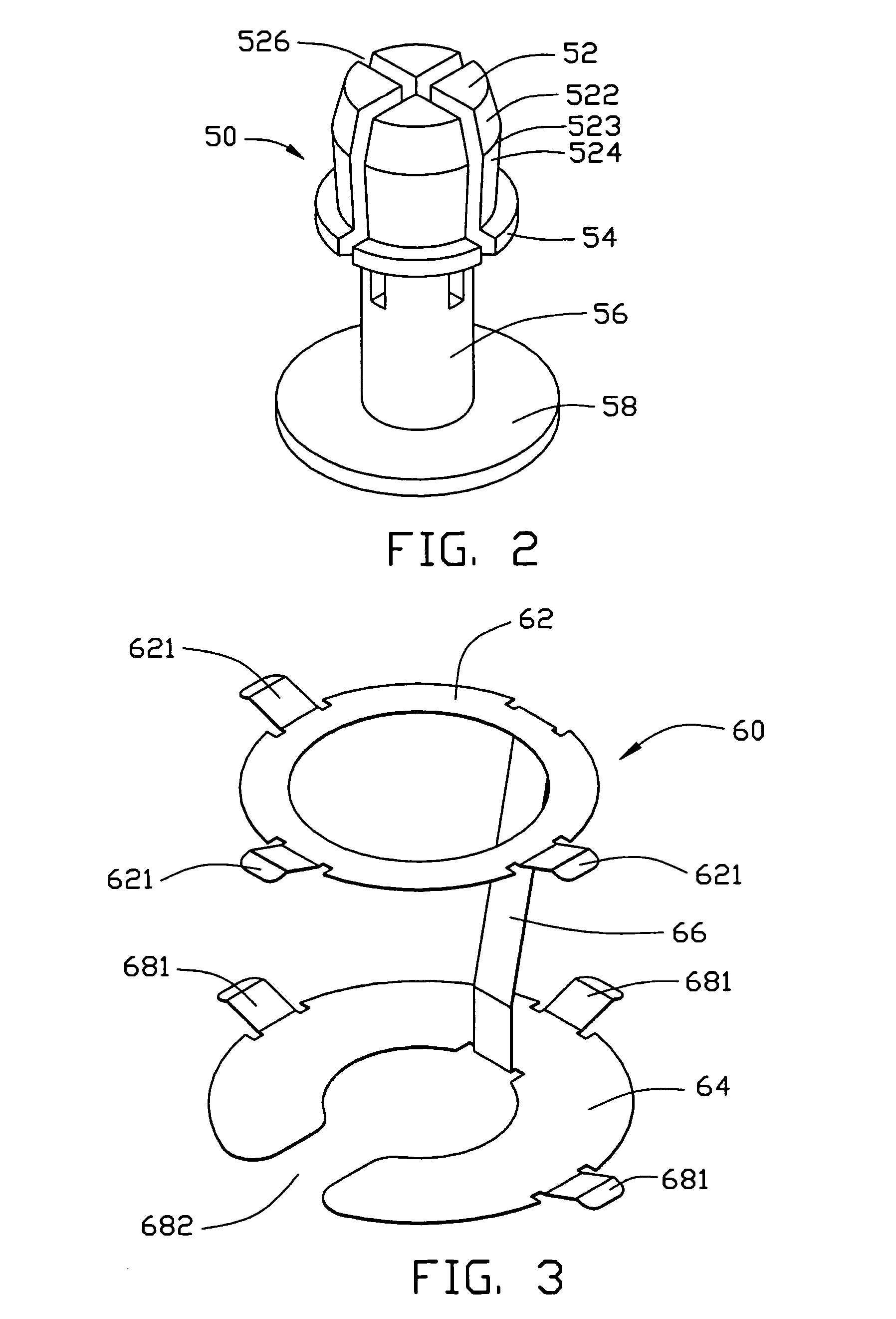
[0018]Referring also to FIG. 2, each standoff 50 is made of conductive material. The s...


PUM


Abstract

A PCB mounting apparatus includes a supporting plate (20) defining a number of through holes, a number of standoffs (50) engaging in the through holes, and a number of grounding members (60) attached to the standoffs. The standoff each includes a head (52) having a holding portion, a flange (54), a post (56), and a base (58). The grounding member each includes a first ring (62) supported on the flange, a second ring (68) supported on the base, and a band (66) connecting therebetween. The PCB (80) defines a number of fixing apertures (82). The combined standoff and grounding member is disposed in the through hole. The PCB is placed upon the supporting plate with the fixing apertures engaging the holding portions of the standoffs and contacts the first rings of the grounding members. The standoffs and the grounding members are made of conductive materials.

Description

BACKGROUND OF THE INVENTION[0001]1. Field of the Invention[0002]The present invention relates to mounting apparatuses for securing a Printed Circuit Board (PCB) in an electronic device, and more particularly to an apparatus which can quickly and readily mounting PCB therein and detaching therefrom.[0003]2. Description of the Related Art[0004]During assembly of a typical personal computer, a PCB such as a motherboard must be fastened to a computer frame or chassis. The motherboard is conventionally mounted to the computer chassis using fasteners such as screws or bolts. China Pat. Nos. 98241276.2 and 00201452.1 each discloses such an arrangement. Coinciding positioning holes are defined respectively in the motherboard and the chassis. The fasteners are inserted and fixed into the coinciding positioning holes, and thereby the motherboard and the chassis are tightened and secured together.[0005]When installing or removing the motherboard, tightening or removing the fasteners is laborio...

Claims


Application Information

Patent Timeline
Patent Type & Authority Patents(United States)
IPC IPC(8): H05K5/02G06F1/18H05K7/14
CPCG06F1/184
Inventor FAN, CHEN-LUCHEN, LI-PING
Owner HON HAI PRECISION IND CO LTD
Why Eureka
Try Eureka