
Tongue swing cylinder arrangement for rotary side-pull mower-conditioner

a rotary side-pull, cylinder arrangement technology, applied in the direction of mowers, agricultural tools and machines, agriculture, etc., can solve the problems of increasing the overall transport width of the mower-conditioner, difficult to provide multiple fixed operating positions, and difficulty in having a low-cost lock for transportation

Inactive Publication Date: 2006-05-23
DEERE & CO
View PDF7 Cites 40 Cited by
  • Summary
  • Abstract
  • Description
  • Claims
  • Application Information

AI Technical Summary

Benefits of technology

[0008]Still another object is to provide a simple lock device for maintaining the cylinder in a fully extended condition for maintaining the tongue in a transport position when it is desired to tow the mower-conditioner along a road, and to provide a simple stop structure for preventing the cylinder from becoming fully retracted so as to position the tongue for operation in other than an extreme or leftmost operating position.

Problems solved by technology

This cylinder placement makes it difficult to have a low-cost lock for transport, as is necessary for holding the cylinder in its retracted position.
It is also difficult to provide multiple fixed operating positions, which are achieved by placing the cylinder in extended positions.
While it is known to provide a mower-conditioner with a tongue having its rear end pivotally mounted to a forward projection of the main frame located at the left side of the header, and to provide an extensible and retractable hydraulic cylinder at the left side of the tongue pivot, this location of the tongue has the disadvantage that it adds to the overall transport width of the mower-conditioner.

Method used


Image

  • Tongue swing cylinder arrangement for rotary side-pull mower-conditioner
  • Tongue swing cylinder arrangement for rotary side-pull mower-conditioner
  • Tongue swing cylinder arrangement for rotary side-pull mower-conditioner

Examples


Embodiment Construction

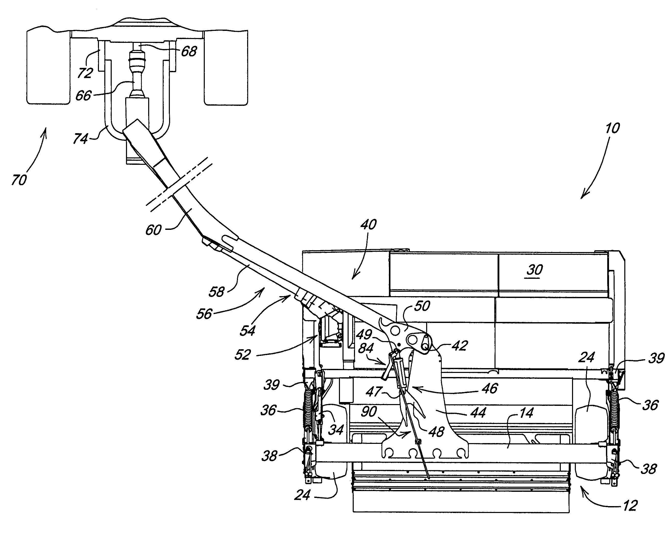
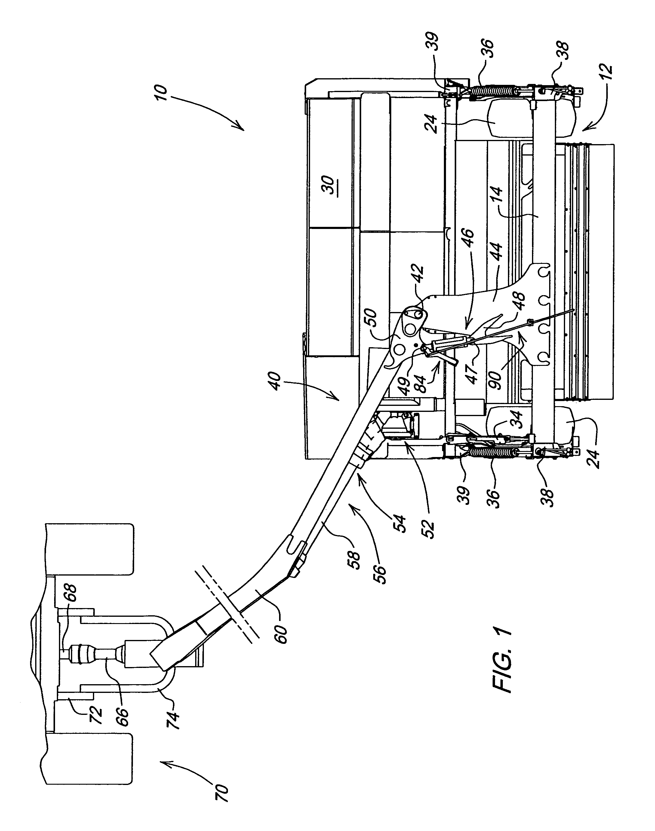
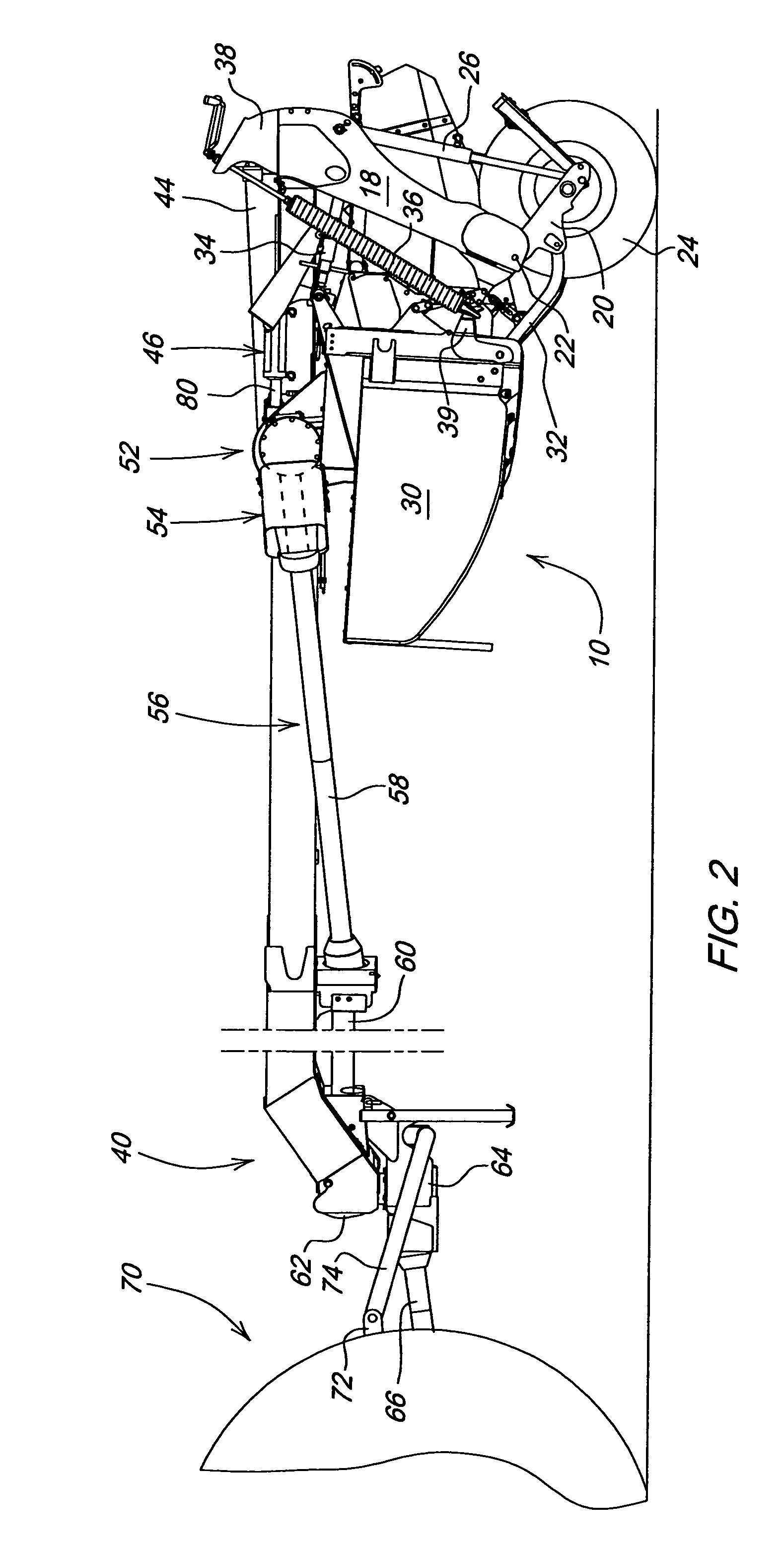
[0014]Referring now to FIGS. 1 and 2, there is shown a rotary side-pull mower-conditioner 10 including a main frame 12 comprising an inverted U-shaped frame member defined by a beam 14 extending transversely between, and joined to right- and left-hand downwardly projecting legs 18. A pair of trailing wheel-support arms 20 have respective forward ends respectively pivotally coupled to the downwardly projecting by transverse pivot pins 22. Mounted to rear regions of each of the support arms 20 is a transverse axle carrying a ground wheel 24. Coupled between each of the legs 18 and the adjacent trailing arm 20 is an extensible and retractable hydraulic actuator 26.

[0015]A crop harvesting header or platform 30 is suspended from the main frame 12 by a linkage including a pair of lower links 32 and an upper link 34, with the lower links 32 being located at opposite ends of the header and coupled between a lower rear region of the header and the adjacent wheel support arm 20, and with the ...


PUM


Abstract

A side-pull mower-conditioner includes a wheeled frame from which a crop harvesting header is suspended. A draft tongue carrier forms a forward projection of the frame and terminates at a forward end located above the header. A draft tongue includes a rear end pivotally coupled to the forward end of the draft tongue carrier by an upright pivot pin defining an upright pivot axis about which the tongue can be swung between a rightmost transport position and a leftmost working position. An extensible and retractable hydraulic actuator is located leftward of the upright pivot axis and is coupled between the draft tongue carrier and the draft tongue and is fully extended when the draft tongue is in the transport position, and is fully retracted when the tongue is in the leftmost working position. A lock structure is provided for locking the actuator in its extended position, and a stop structure is provided for selectively limiting the retraction of the actuator for disposing the tongue in a desired working position which is rightward of the leftmost working position.

Description

FIELD OF THE INVENTION[0001]The present invention relates to a rotary side-pull mower-conditioner, and more particularly, relates to a tongue swing cylinder arrangement for use with the mower-conditionerBACKGROUND OF THE INVENTION[0002]Side-pull rotary mower-conditioners typically use a tongue swing cylinder mounted to the right of the tongue pivot. Thus, in order to swing the tongue outwardly to a normal working position where the towing tractor travels a path to the left of the standing crop being cut by the mower-conditioner, the cylinder must be extended from a fully retracted position, which it occupies when the tongue is in a central position for permitting the transport of the mower-conditioner.[0003]This cylinder placement makes it difficult to have a low-cost lock for transport, as is necessary for holding the cylinder in its retracted position. It is also difficult to provide multiple fixed operating positions, which are achieved by placing the cylinder in extended positio...

Claims


Application Information

Patent Timeline
Patent Type & Authority Patents(United States)
IPC IPC(8): A01D34/24A01D34/42A01D34/63
CPCA01D75/004A01D34/64
Inventor STEPHENSON, ROGER DALEROE, ANNETTE RAE
Owner DEERE & CO
Learn More