Combination lock and padlock combination

Inactive Publication Date: 2006-05-23
LIN FU CHUAN
View PDF12 Cites 54 Cited by
  • Summary
  • Abstract
  • Description
  • Claims
  • Application Information

AI Technical Summary

Benefits of technology

[0005]It is therefore an object of the present invention to provide a combination lock and padlock combination as a lock comprising a housing comprising a cover including a window proximate edge and a plurality of wheel openings, and a base including a first shackle receiving hole, a second shackle receiving hole parallel and opposing the first shackle receiving hole, and a cavity proximate the second shackle receiving hole; a tumbler wheel assembly disposed in the base and comprising a plurality of tumbler wheels each partially projected from the wheel opening and having a plurality of slots along its inner surface, a cylindrical moveable bar inserted through the tumbler wheels, the bar including a forward extension, and a plurality of lengthwise locking fins on its surface, the locking fins being aligned, snugly fitted in the slots and interlocked engaged therewith; a locking mechanism disposed in the base and comprising a U-shaped member fixedly connected to the forward extension of the bar, the U-shaped member including two rectangular channels on both sides, a rectangular shuttle member including a central opening, a projection at one side, a spring biased extension at the other side, the extension being inserted through the channels until being stopped by a shoulder between itself and the shuttle member with the spring of the extension being biased between both sides of the U-shaped member, and an arcuate recess formed at an end of the extension, and a parallelepiped indicator assembly fitted in the cavity and including a latch at one side proximate the projection, an internal spring having one end urged against a wall of the cavity, and a knurled indicating face on its top; a U-shaped shackle comprising one leg received in the second shackle receiving hole in a locked position, the other leg having an annular groove proximate a terminating end thereof and received in the first shackle receiving hole, the groove being in contact with the recess, and a spring depressible detent being pressed into the housing in a locked position; and a cylindrical key turning assembly disposed in the base and comprising a rectangular side ridge, a keyhole, and a forward bar-shaped protrusion having half of its forward portion being cut, the forward portion of the protrusion inserted through the central opening until a shoulder between itself and a rear portion thereof is stopped, whereby turning the tumbler wheels will turn the locking fins until a correct combination i...

Problems solved by technology

This is inconvenient especial...

Method used


Image

  • Combination lock and padlock combination
  • Combination lock and padlock combination
  • Combination lock and padlock combination

Examples


Embodiment Construction

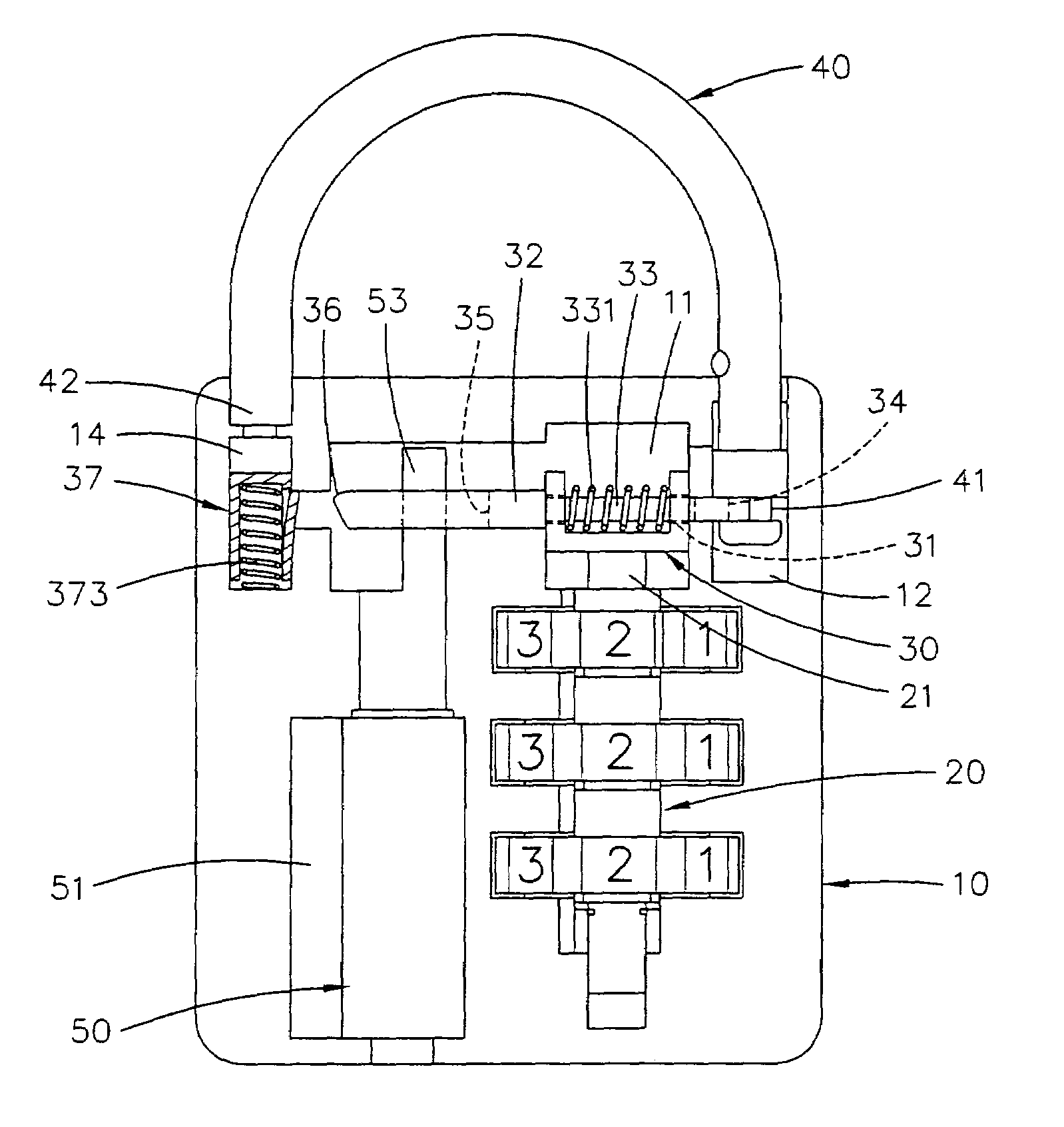
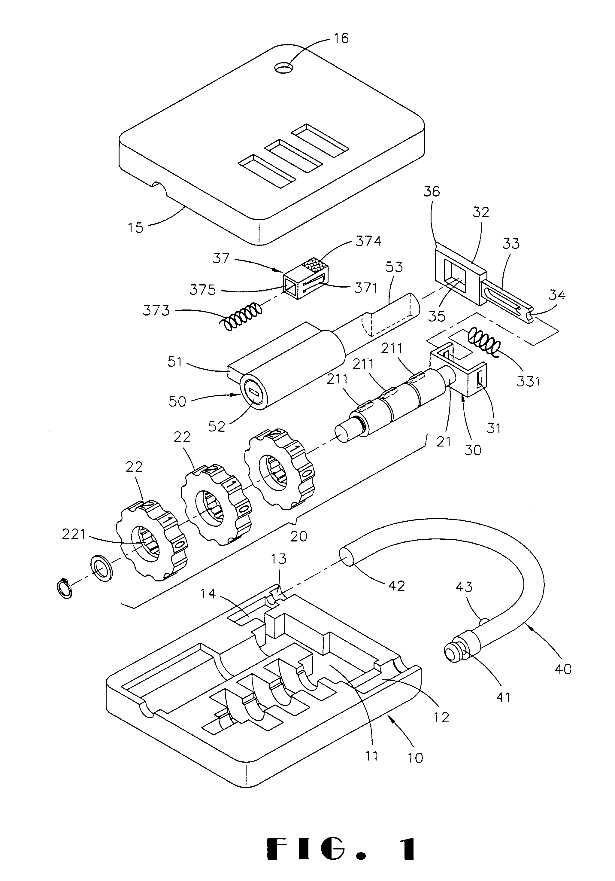
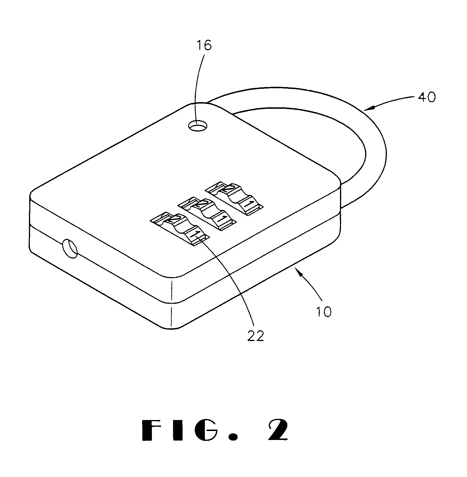
[0016]Referring to FIGS. 1, 2, and 3, a combination lock and padlock combination (i.e., lock) constructed in accordance with the invention is shown and comprises a housing 10, a tumbler wheel assembly 20, a locking mechanism 30, a U-shaped shackle 40, and a key turning assembly 50. Each component will be described in detail below.

[0017]The parallelepiped housing 10 comprises a cover 15 having an window 16 proximate one of its four corners, and a base including a first hole 12 proximate one of its four corners, a second hole 13 proximate the other corner opposing the first hole 12, a cavity 14 proximate the second hole 13, and an internal space 11 between the first hole 12 and the cavity 14.

[0018]The tumbler wheel assembly 20 is anchored in a series of half-circular recesses on the base of the housing 10 in communication with each other and comprises three tumbler wheels 22 each having a plurality of slots 221 along its inner surface, a cylindrical moveable bar 21 fitted in the tumbl...


PUM


Abstract

Provided is a combination lock and padlock combination comprising a housing include a window; a tumbler wheel assembly; a cylindrical moveable bar inserted through the tumbler wheels; a locking mechanism including a U-shaped member fixed at the bar, a rectangular shuttle member having a central opening, a projection at one side, a spring biased extension at the other side inserted through the shuttle member, and an arcuate recess at an end of the extension, and a parallelepiped indicator assembly fitted in a cavity proximate a shackle receiving hole and including a latch, an internal spring having one end urged against a wall of the cavity, and an indicating face on its top; a U-shaped shackle having an annular groove proximate one end being in contact with the recess; and a cylindrical key turning assembly co-acted with the shuttle member.

Description

BACKGROUND OF THE INVENTION[0001]1. Field of Invention[0002]The present invention relates to combination locks and more particularly to a combination lock capable of being opened by inserting a key into keyhole in addition to turning tumbler wheels to a set series of numbers for opening.[0003]2. Related Art[0004]Locks with features of both pad lock and combination lock are well know. Conventionally, in a key opening operation of the lock a person has to turn a key inserted into a keyhole with one hand and pull a shackle out of a housing for opening with the other hand. This is inconvenient especially when only one hand is available. Also, there is a need of providing means on a combination lock and padlock combination for informing other persons (e.g., customs officer) that a luggage, a container or the like being locked by the combination lock and padlock combination has been opened previously for inspection so that a further opening of the same is not necessary. However, such feat...

Claims


Application Information

Patent Timeline
IPC IPC(8): E05B37/10
CPCE05B39/00E05B37/025E05B37/0034E05B67/24Y10T70/424Y10T70/7407Y10T70/8027
Inventor LIN, FU CHUAN
Owner LIN FU CHUAN
Why Eureka
Try Eureka