Liquid detection sensor and liquid detection apparatus

a liquid detection sensor and liquid detection technology, applied in the direction of mechanical actuation of burglar alarms, instruments, and using reradiation, can solve the problems of not restoring the original volume, the cost of expensive liquid detection sensors increases, and the practical value of the present invention is extremely high. , the effect of rapid progress in valu

Inactive Publication Date: 2006-05-23
PANASONIC CORP
View PDF15 Cites 70 Cited by
  • Summary
  • Abstract
  • Description
  • Claims
  • Application Information

AI Technical Summary

Benefits of technology

[0012]A primary objective of the present invention is to provide a liquid detection sensor which is small, inexpensive and reusable.
[0013]A secondary objective of the present invention is to provide a liquid detection apparatus which can accurately detect a condition of the liquid detection sensor even when a resonant frequency of the liquid detection sensor is dispersed.

Problems solved by technology

However, because the conventional liquid detection sensors are structured to have a switch SW having a complex configuration, it becomes costly as it gets bigger.
Therefore, once the material absorbs water, it does not restore its original volume as it looses elasticity.
As a result, the expensive liquid detection sensor cannot be reused.
Consequently, because a subtle level change cannot be detected with the conventional method that compares two values in the liquid detection apparatus, it is not possible to accurately detect the condition of the liquid detection sensor.

Method used


Image

  • Liquid detection sensor and liquid detection apparatus
  • Liquid detection sensor and liquid detection apparatus
  • Liquid detection sensor and liquid detection apparatus

Examples


first embodiment

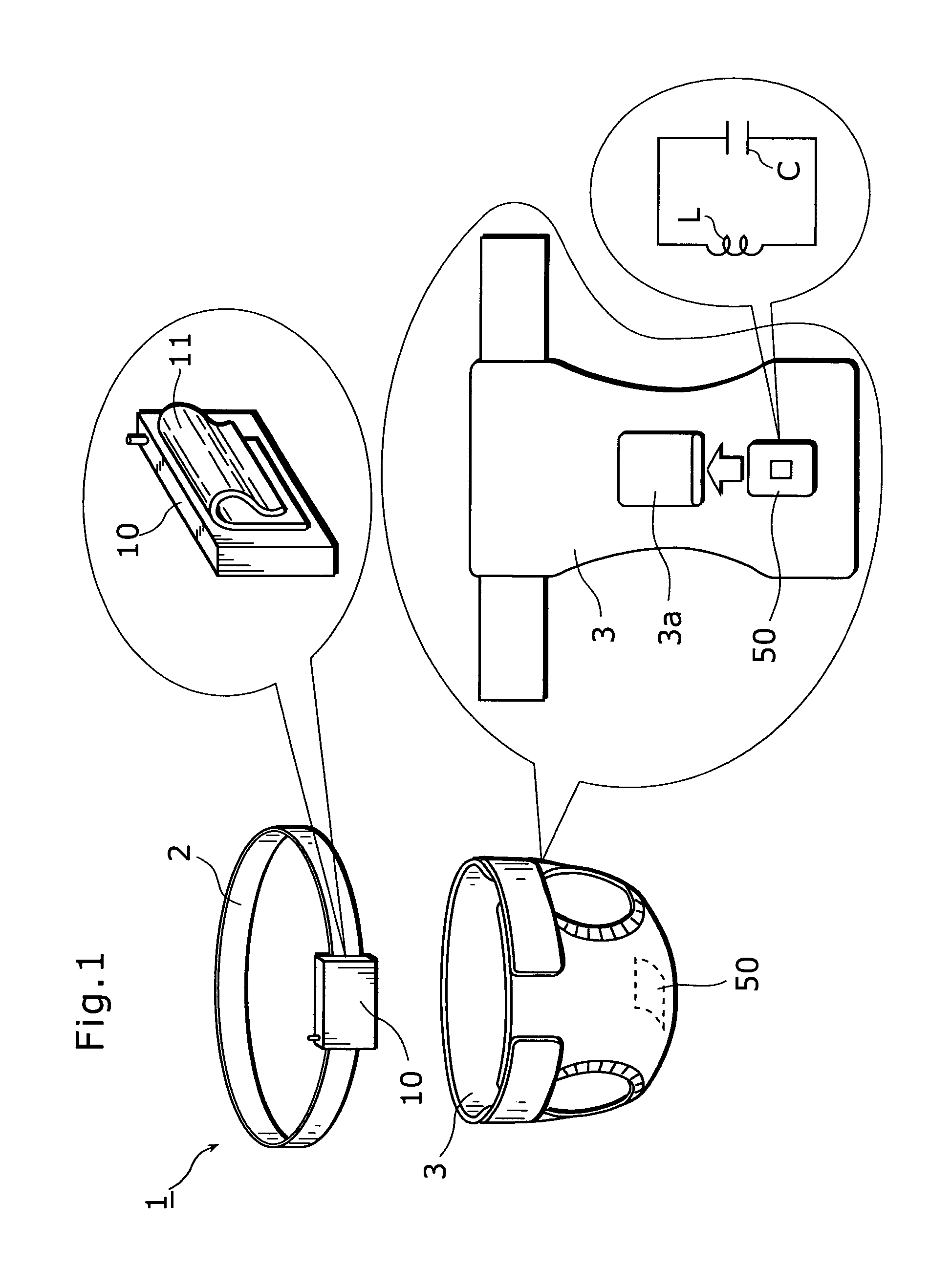
[0041]FIG. 1 is a diagram showing an overall configuration for a case in which the liquid detection system related to the first embodiment is applied to detecting incontinence.

[0042]As shown in the diagram, a moisture detection system (a liquid detection system) 1 comprises a diaper 3, a moisture detection sensor (a liquid detection sensor, a noncontact tag) 50 attached to this diaper 3, a belt 2 and a moisture detection apparatus (a liquid detection apparatus, a tag reader apparatus) 10 attached to this belt 2.

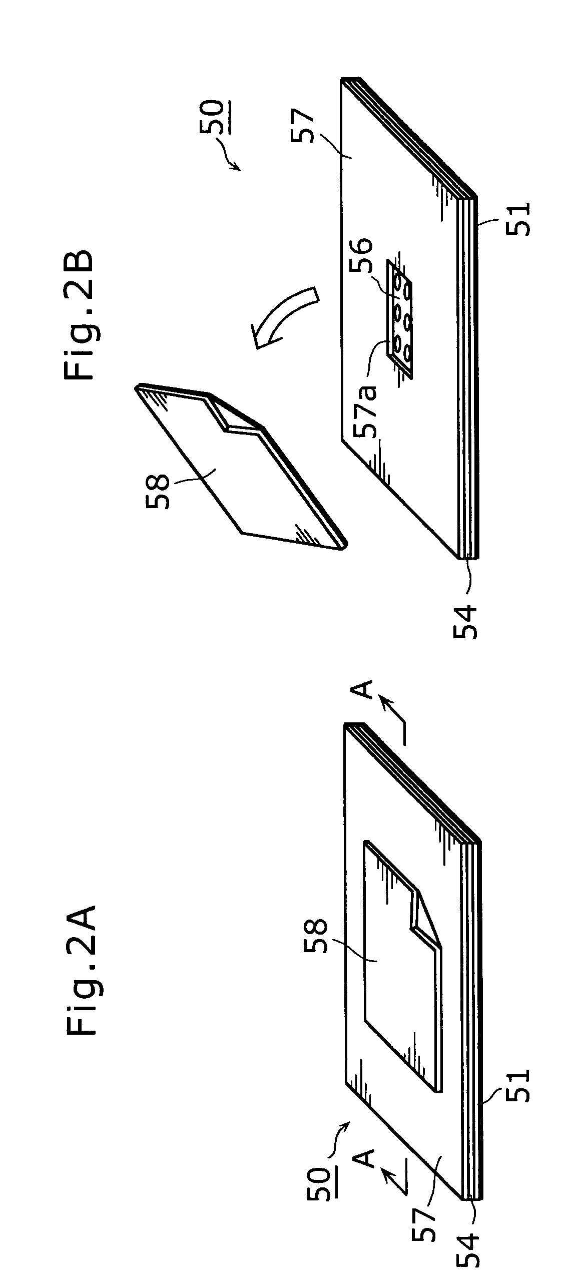
[0043]A pocket 3a is provided for attaching the moisture detection sensor 50 at a center part of the diaper 3 where liquid detection is performed, and the moisture detection sensor 50 is inserted into an inside of the pocket 3a from an opening of this pocket 3a. The diaper 3 where the moisture detection sensor 50 is inserted is attached to a person who needs care (a care-recipient) such as a baby or an elderly person. The moisture detection sensor 50 is a noncontact tag inclu...

second embodiment

[0077]The following describes a configuration of another moisture detection sensor related to a second embodiment of the present invention.

[0078]In the moisture detection sensor 50 related to the first embodiment mentioned above, the pocket 3a is formed on the diaper 3, and the moisture detection sensor 50 is inserted into this pocket 3a. In this case, it requires extra work because an opening part of the pocket 3a needs to be opened to attach the moisture detection sensor 50.

[0079]Therefore, as shown in FIG. 11, the moisture detection sensor 50 related to the second embodiment is structured so that it can be attached by a planar fastener. In particular, one surface of the planar fastener (e.g. a loop material 59a) is attached to a lower surface of the covering material 51 and the other surface of the planar fastener (e.g. a hook material 59b) is attached to the diaper 3, which allows the moisture detection sensor 50 to be attached and detached easily. Therefore, unlike the first em...

third embodiment

[0080]The following describes a configuration of another moisture detection sensor related to a third embodiment of the present invention.

[0081]In the moisture detection sensor 50 related to the first and second embodiments, the antenna coil 53 in a planar shape is formed on a plane surface. In this structure, when an antenna surface of the moisture detection apparatus 10 is located in parallel with a tag surface formed by the antenna coil 53, a maximum communication range is obtained. In other words, within a certain distance, when the antenna surface and the tag surface are located in parallel, a maximum electromagnetic induction is generated, and there is a direction dependency in detection sensitivity. Therefore, when the tag leans to one side, the electromagnetic induction level falls down, and it may be difficult to specify the resonant frequency in the initialization mode or in the detection mode.

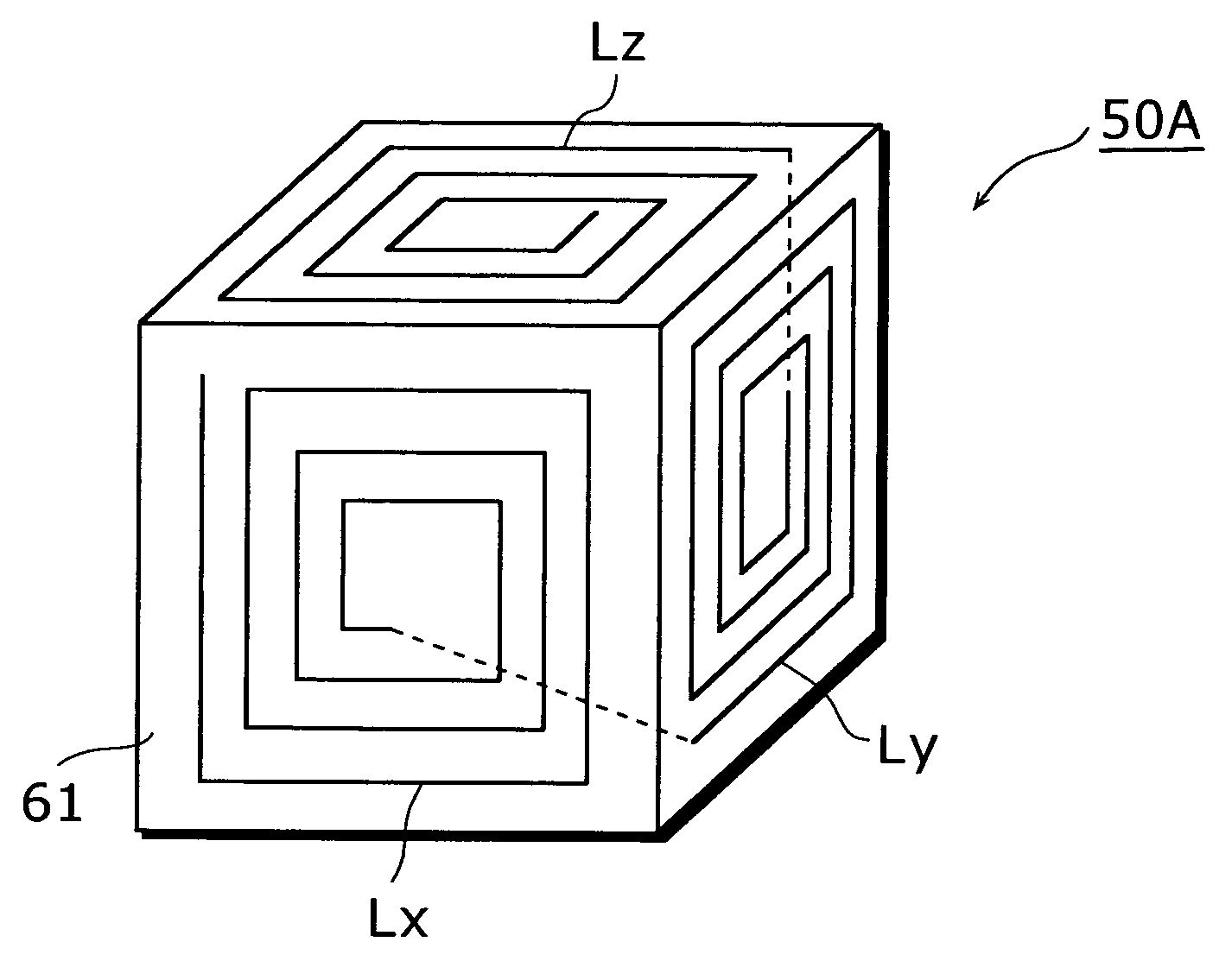
[0082]The moisture detection sensor related to the third embodiment of the prese...


PUM

PropertyMeasurementUnit
capacitanceaaaaaaaaaa
relative permittivityaaaaaaaaaa

Abstract

A moisture detection sensor includes a resonant circuit composed of an antenna coil 53 and a capacitor C. A noncontact tag composed of covering materials 51 and 57 covers the resonant circuit. The capacitor C has a pair of electrodes 52 and 56 and a dielectric 55 interposed between the electrodes 52 and 56, and the covering material 57 contains a through-hole 57a that allows the liquid to infiltrate into the dielectric 55 from outside.

Description

BACKGROUND OF THE INVENTION[0001](1) Field of the Invention[0002]The present invention relates to a liquid detection sensor, a liquid detection apparatus, and a liquid detection system using the sensor and the apparatus.[0003](2) Description of the Related Art[0004]Along with recent aging society, various care supplies such as paper diapers and apparatuses detecting incontinence have been developed. As one of the apparatuses, for example, the Japanese Laid Open Patent Nos. 2001-289775 and 2001-325865 disclose a liquid detection sensor using a noncontact tag method and a liquid detection apparatus that detects a state of the liquid detection sensor without contacting the sensor.[0005]The liquid detection sensor disclosed in the above documents comprises a coil L, a capacitor C and a switch SW, and has a configuration example in which these components are connected in series in a loop shape (hereinafter this configuration example is referred to as a “first conventional configuration e...

Claims


Application Information

Patent Timeline
Patent Type & Authority Patents(United States)
IPC IPC(8): G08B23/00G01V3/00A61F5/44A61F13/42A61F13/49G01M3/16G01N22/00G01N22/04G01N27/00G01N27/22G01R27/26G01V15/00
CPCA61F13/42G01N27/225G01M3/16
Inventor TAMAI, SEIICHIRO
Owner PANASONIC CORP
Why Eureka
Try Eureka